
Directional soft tissue dilator and docking pin with integrated light source for optimization of retractor placement in minimally invasive spine surgery

a soft tissue dilator and docking pin technology, applied in the field of orthopaedic surgery, can solve the problems of long healing time, damage to muscle tissue, and significant blood loss, and achieve the effect of preferential dilation and facilitate preferential dilation of tissues

Inactive Publication Date: 2010-05-06
UNIVERSITY OF TOLEDO
View PDF44 Cites 183 Cited by
  • Summary
  • Abstract
  • Description
  • Claims
  • Application Information

AI Technical Summary

Benefits of technology

This patent describes a new system for inserting a cannula and working port for minimally invasive spinal surgery. The system allows for preferential dilatation in a more desirable location, while avoiding excessive stretching of vital tissues. The dilator system can be used with existing tools and can be interchanged with other dilators. The system also includes a combined light source and docking pin for retention of the retractor blades in the desired location during the surgical procedure. The docking pin with integrated locking system is disposable and can be made of variable lengths to fit all sizes and body habitus. Overall, the system improves the precision and effectiveness of spinal surgery procedures.

Problems solved by technology

This patent describes improvements to tools used in spine surgery to reduce injury and improve effectiveness. Specifically, there are new designs for a soft tissue dilator (a tool used to expand the space between two parts) and a docking pin (which helps hold another device called a retractor). Current versions have limitations including difficulty in accurate placement and causing unwanted stress on nerve cells. The new design provides better control and flexibility during surgery.

Method used


Image

  • Directional soft tissue dilator and docking pin with integrated light source for optimization of retractor placement in minimally invasive spine surgery
  • Directional soft tissue dilator and docking pin with integrated light source for optimization of retractor placement in minimally invasive spine surgery
  • Directional soft tissue dilator and docking pin with integrated light source for optimization of retractor placement in minimally invasive spine surgery

Examples


first embodiment

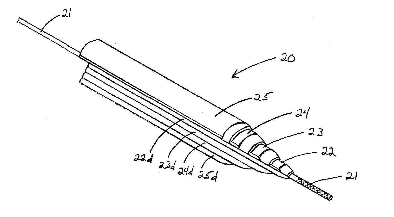
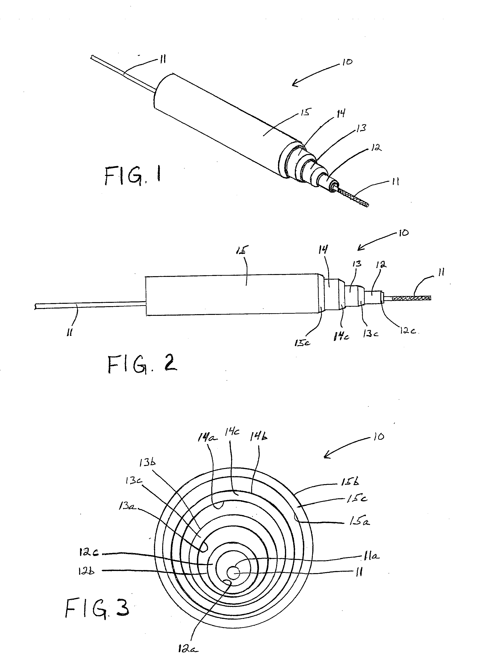
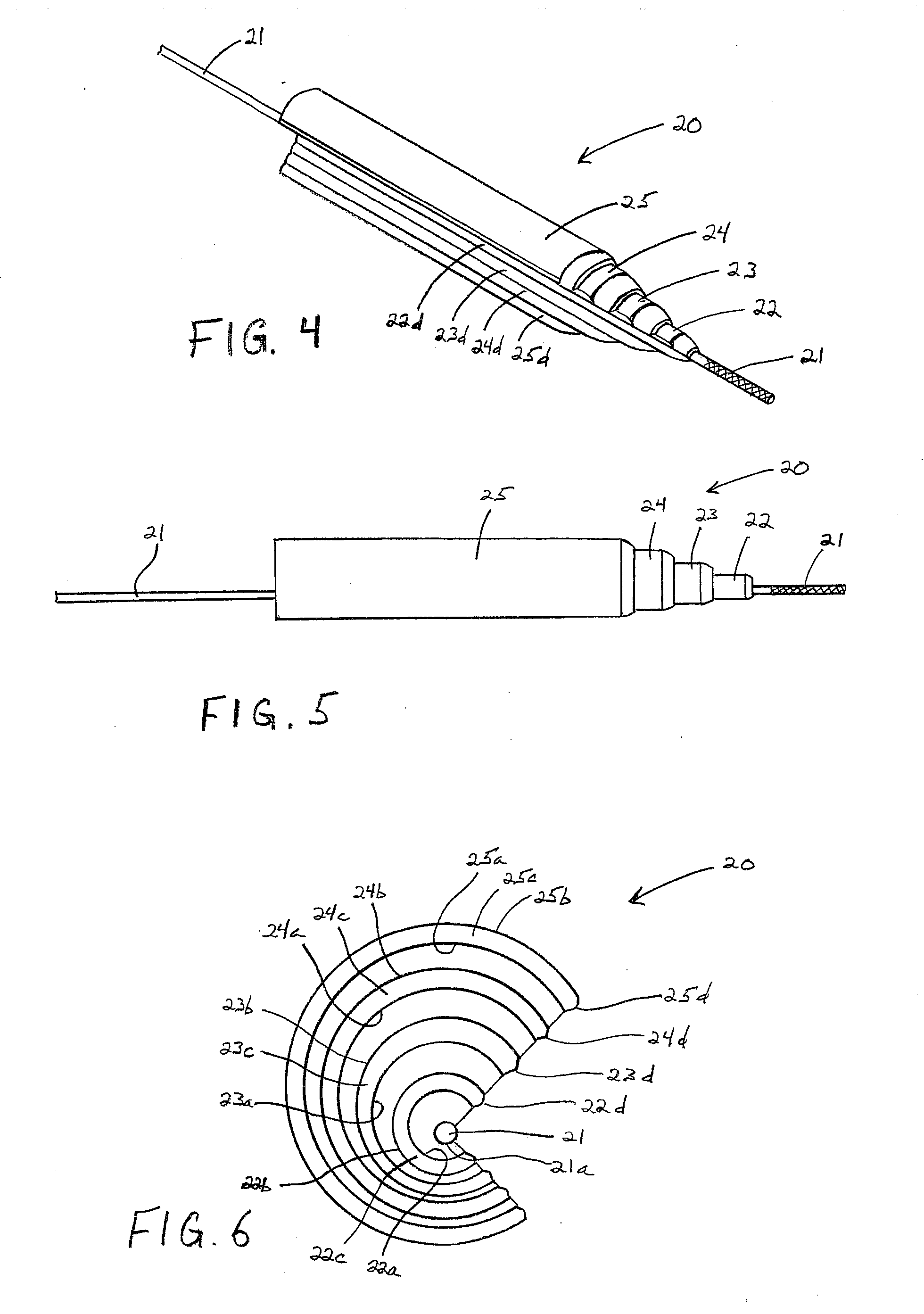
[0033]the dilator 10 also includes a second dilator member 12 that is disposed about and supported on the first dilator member 11 for both axial and rotational sliding movement relative thereto. The second dilator member 12 is hollow and includes an inner surface 12a and an outer surface 12b. In the illustrated embodiment, both the inner surface 12a and the outer surface 12b of the second dilator member 12 are each generally cylindrical in shape and, therefore, define respective cross-sectional shapes that are generally circular and define respective axes, as best shown in FIG. 3. However, as also shown in FIG. 3, the inner surface 12a and the outer surface 12b are not oriented concentrically relative to one another. Rather, the wall thickness of the second dilator member 12 varies circumferentially such that the inner surface 12a and the outer surface 12b are oriented eccentrically relative to one another. The purpose for this eccentric orientation will be explained below. In the i...

third embodiment

[0041]FIG. 7 illustrates a dilator member, indicated generally at 30, of a soft tissue dilator in accordance with this invention. The dilator member 30 is hollow and includes an inner surface 30a and an outer surface 30b. In the illustrated embodiment, both the inner surface 30a and the outer surface 30b of the dilator member 30 are generally cylindrical in shape and, therefore, define respective cross-sectional shapes that are circular. In this embodiment of the invention, however, the inner surface 12a and the outer surface 12b are oriented concentrically relative to one another. Thus, the wall thickness of the dilator member 30 does not vary circumferentially. Rather, a plurality of projections 30c, 30d, 30e, and 30f are provided on the inner surface 30a of the dilator member 30.

[0042]In the illustrated embodiment, four of such projections 30c, 30d, 30e, and 30f are provided on the inner surface 30a of the dilator member 30. However, it will be appreciated that this invention may...


PUM


Abstract

A soft tissue dilator for use in a surgical procedure includes a first dilator member that defines a first axis and a second dilator member that defines a second axis. The second dilator member is supported on the first dilator member such that relative rotational movement of the first and second dilator members causes eccentric movement of the first and second axes defined by the first and second dilator members. Additional dilators members may be sequentially supported on the first and second dilator members.

Description


Claims


Application Information

Patent Timeline
Owner UNIVERSITY OF TOLEDO
Learn More