Rail vehicle or other path-constrained vehicle equipped for providing solar electric power for off-vehicle use, and systems in support thereof

a technology for solar electric power and rail vehicles, applied in the direction of electric devices, light-to-electric conversion, instruments, etc., can solve the problems of public electric power grid, inability to respond to electric power demand, and inability to improve the situation

Inactive Publication Date: 2010-05-06
PLISHNER PAUL J
View PDF0 Cites 10 Cited by
  • Summary
  • Abstract
  • Description
  • Claims
  • Application Information

AI Technical Summary

Benefits of technology

[0017]The invention has especial merit in that at least some kinds of rail vehicles, notably trolley cars or individual cars or even engines of electric trains, are increasingly likely to include solar collectors for providing at least some electric power for their own use (or the train's use), even if such vehicles also derive electric power from an external source such as the grid. With the invention, any excess power such a rail car might generate using its solar collectors can be saved to for example the grid, instead of going to waste.

Problems solved by technology

The public electric power grid is, from time to time, unable to respond to demands for electric power.
The situation is not likely to improve, on account of increasing population with attendant increase in demand.
In addition, while sources of electric power (power-generation facilities) traditionally relied on by the grid do currently provide the electric power we need, they typically do so using fossil fuels, at the risk of contributing to global warming.
Solar power collectors are already being used to some extent to contribute power to the power grid, but the cost of solar collectors has argued against such use in other than large-scale applications in very favorable environments.
Of course, there would be cost associated with providing and maintaining the equipment needed by the rail vehicle or other path-constrained vehicle for producing the solar electric power.

Method used


Image

  • Rail vehicle or other path-constrained vehicle equipped for providing solar electric power for off-vehicle use, and systems in support thereof
  • Rail vehicle or other path-constrained vehicle equipped for providing solar electric power for off-vehicle use, and systems in support thereof
  • Rail vehicle or other path-constrained vehicle equipped for providing solar electric power for off-vehicle use, and systems in support thereof

Examples


Embodiment Construction

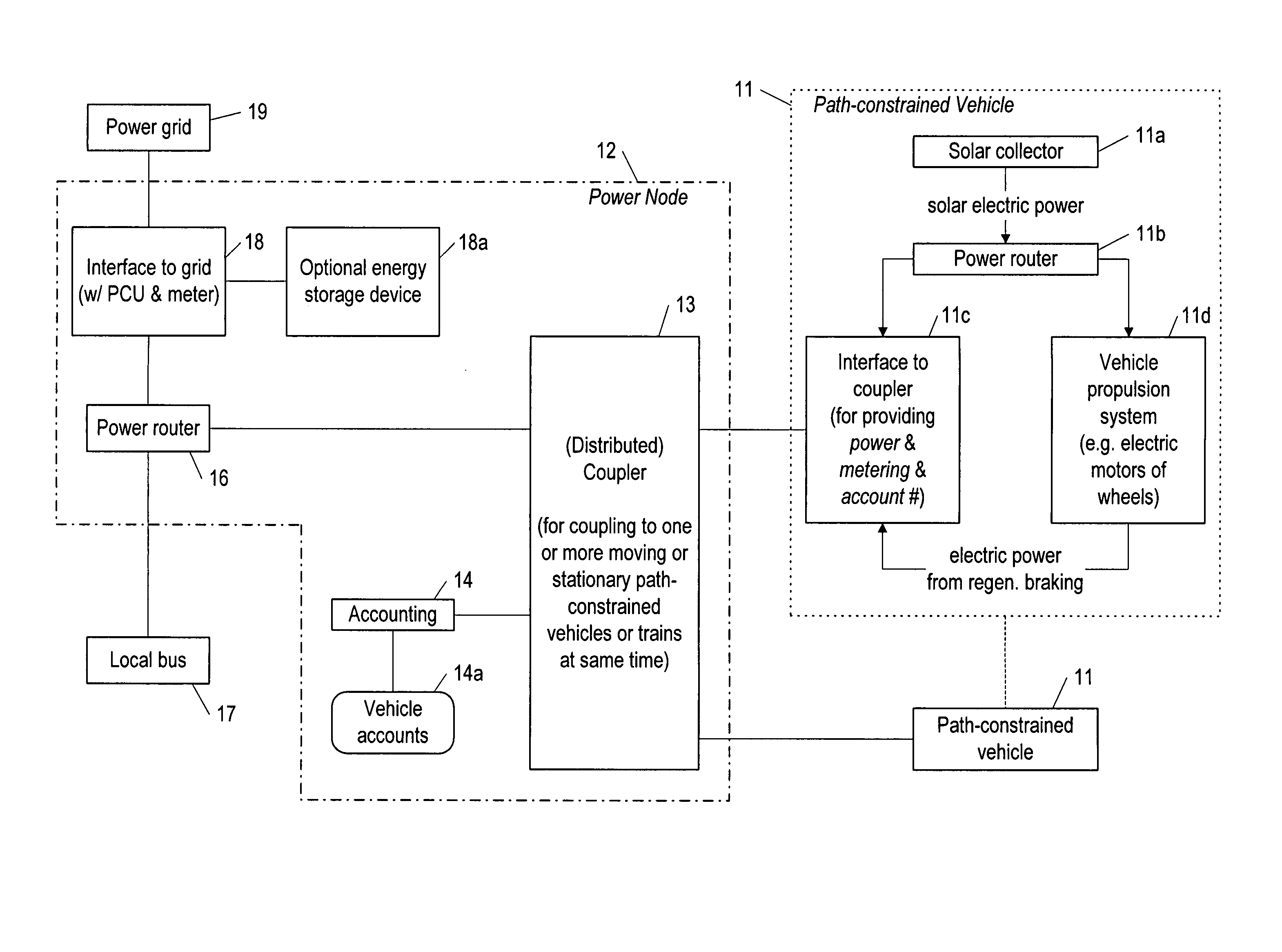
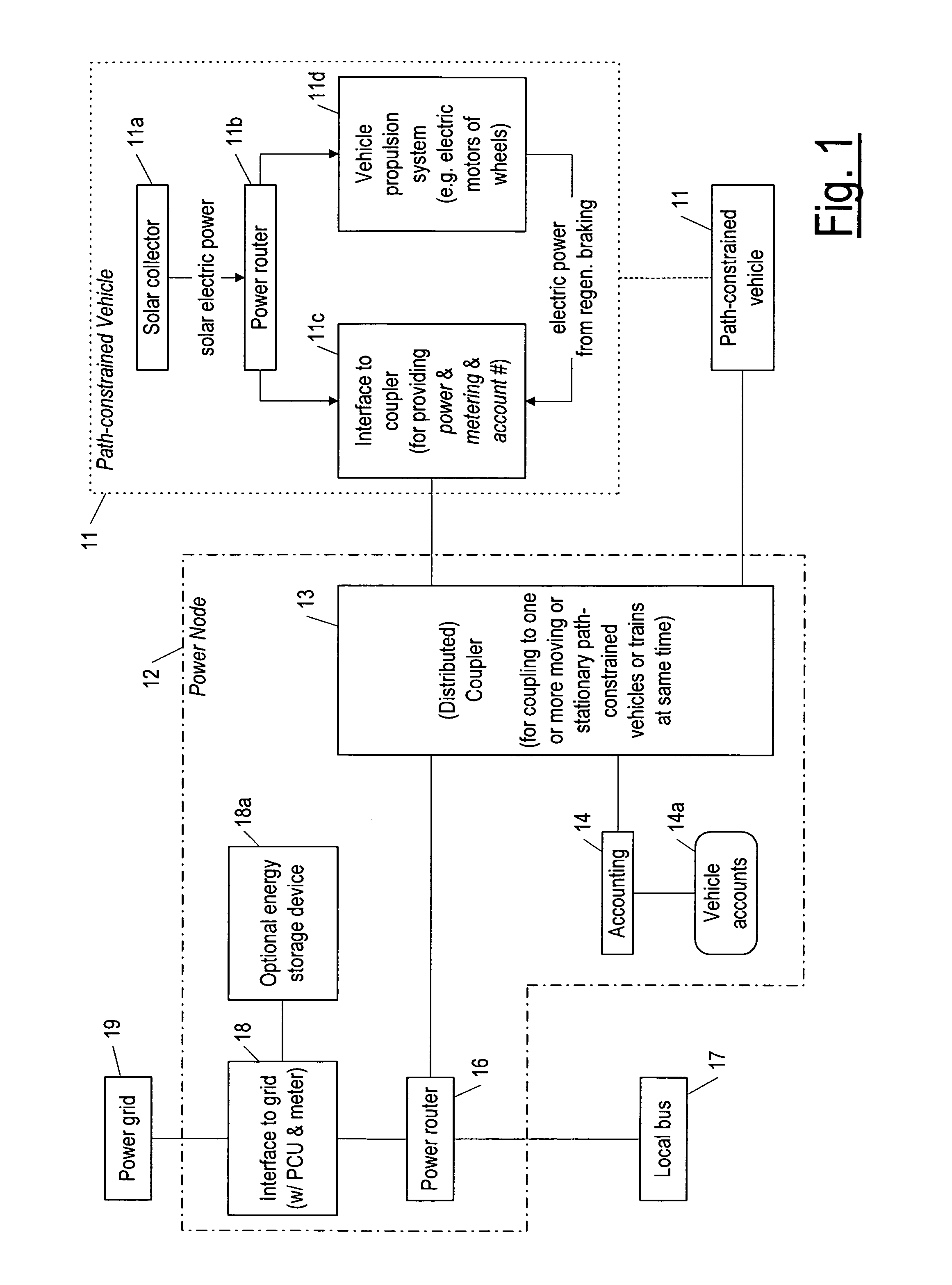
[0024]The term path-constrained vehicle is used here to mean a vehicle that moves along a rail, a vehicle that moves along a guideway as in a maglev train system, or a wheeled vehicle that must follow a catenary in order to receive electric power from the catenary for powering the vehicle. The term “train” as used here is intended to encompass any single such vehicle or any plurality of such vehicles connected in tandem. As used here, a train should be understood to encompass a railway, a rail line, a commuter line, and a freight line (any one of which may be a train that rolls, or a train that is magnetically levitated).

[0025]Thus, a path-constrained vehicle can include a trolley car or any other kind of rail vehicle that is unconnected to other vehicles in tandem but moves along a rail or guideway, or a car in a train of cars pulled by an engine, or a vehicle of a maglev train, or a wheeled bus that must be steered so as to follow a catenary system from which it receives electric ...


PUM


Abstract

A method by which a path-constrained vehicle (or series of such vehicles), constrained to travel along a rail or guideway of a magnetic levitation system or to follow a catenary, is equipped to provide electric power derived for off-vehicle use derived from solar collectors formed or provided on the surface of the vehicle. The solar electric power is provided to a coupling system distributed proximate to the rail or guideway or catenary and / or provided as part of same. The coupling system then provides the power for possible use by the public electric power grid or other off-vehicle use, and may compensate the vehicle (or train of vehicles) for the electric power.

Description

CROSS REFERENCE TO RELATED APPLICATIONS[0001]This application is a divisional of U.S. patent application Ser. No. 11 / 594,038 filed Nov. 6, 2006, from which priority is claimed under all applicable sections of Title 35 of the United States Code including, but not limited to, Sections 120, 121, and 365(c).BACKGROUND OF THE INVENTION[0002]1. Technical Field[0003]The invention pertains to the field of electric power generation. More particularly, the invention concerns a rail vehicle, such as a freight car or passenger car of a train, providing electric power from solar collectors formed on the body of the vehicle, for use by for example the public power grid, and doing so while the vehicle is either stationary or in motion. The invention also concerns other kinds of path-constrained vehicles providing solar electric power for off-vehicle use, such as maglev vehicles and wheeled buses that must follow a catenary to receive electric power for propulsion.[0004]2. Discussion of Related Art...

Claims


Application Information

Patent Timeline
Patent Type & Authority Applications(United States)
IPC IPC(8): G06F17/00
CPCB60M3/06B60L53/665Y02T10/7005Y02T10/7083Y02T90/14B60L8/003Y02T10/7072B60L2200/26B60L2240/70Y02T90/16Y02T90/163Y02T90/169Y02T10/7291Y02T90/121Y02T90/128Y04S10/126Y04S30/14Y02E60/721B60L53/14B60L55/00G06Q50/06Y02E60/00Y02T10/72Y02T90/12Y02T90/167Y02T10/70
Inventor PLISHNER, PAUL J.
Owner PLISHNER PAUL J
Why Eureka
Try Eureka