
Method and system for managing energy efficiency of a network link via pluggable transceiver modules in an energy efficient network device

a technology of pluggable transceiver modules and network link, applied in the field of network connection, can solve problems such as significant increases in power consumption

Inactive Publication Date: 2010-05-06
AVAGO TECH WIRELESS IP SINGAPORE PTE
View PDF47 Cites 40 Cited by
  • Summary
  • Abstract
  • Description
  • Claims
  • Application Information

AI Technical Summary

Benefits of technology

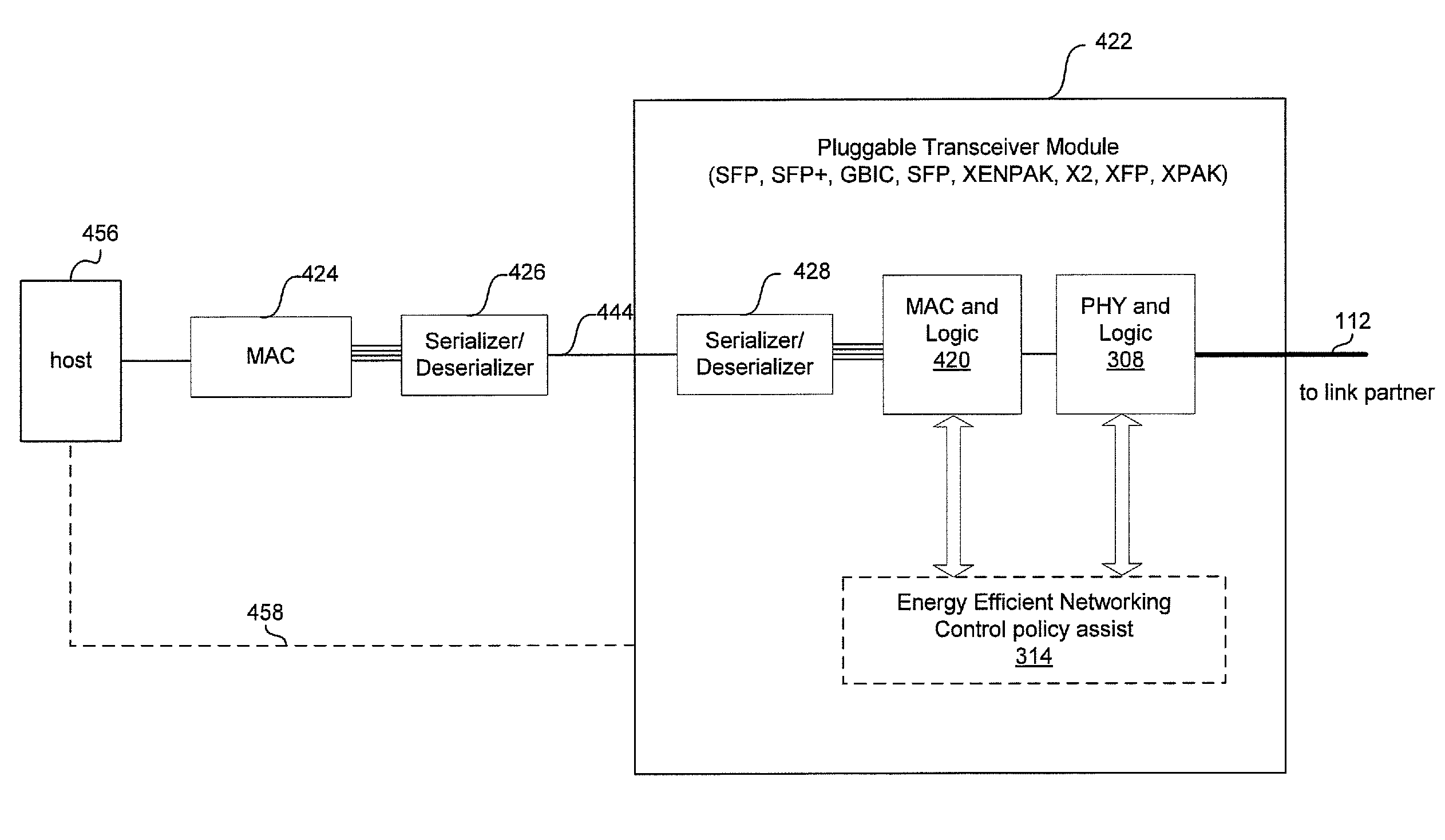
[0020]FIG. 5 is a flow chart illustrating exemplary steps implementing an energy efficient network control policy in a pluggable physical layer device, in accordance with an embodiment of the invention.

Problems solved by technology

Conventionally, however, increased data rates often results in significant increases in power consumption.

Method used


Image

  • Method and system for managing energy efficiency of a network link via pluggable transceiver modules in an energy efficient network device
  • Method and system for managing energy efficiency of a network link via pluggable transceiver modules in an energy efficient network device
  • Method and system for managing energy efficiency of a network link via pluggable transceiver modules in an energy efficient network device

Examples


Embodiment Construction

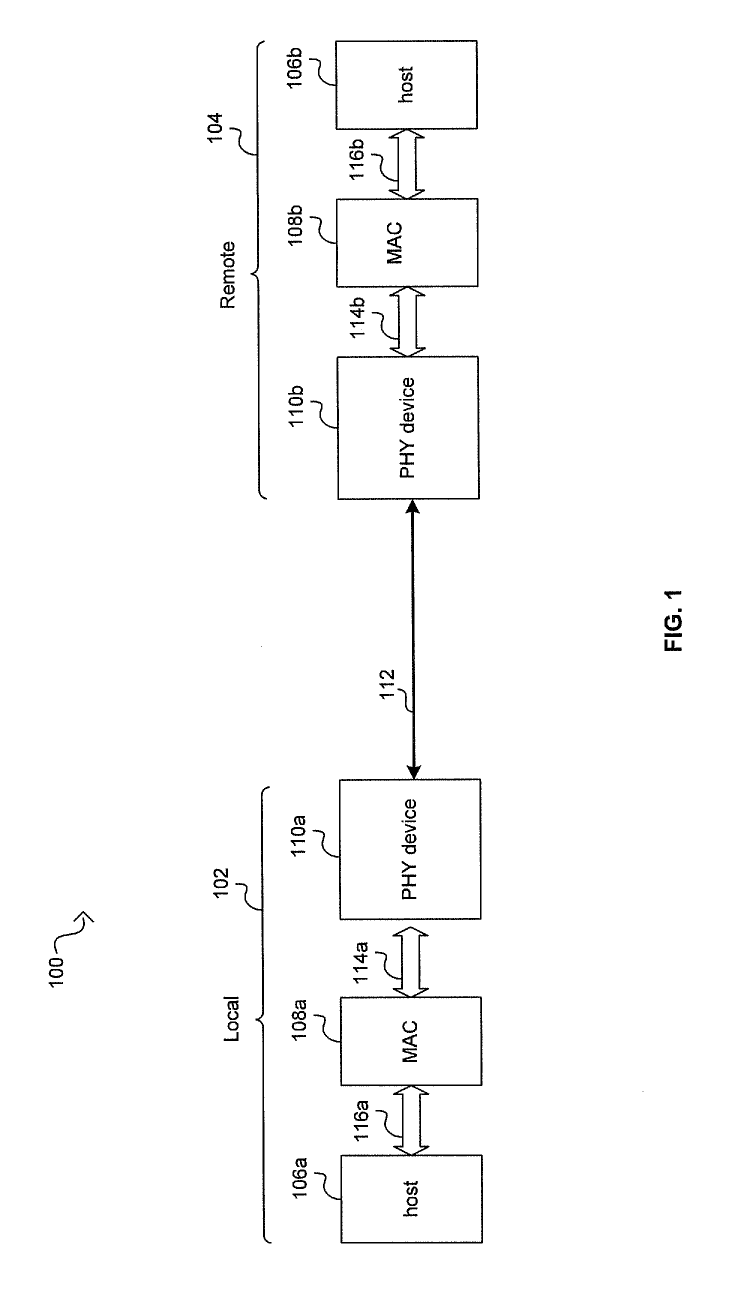
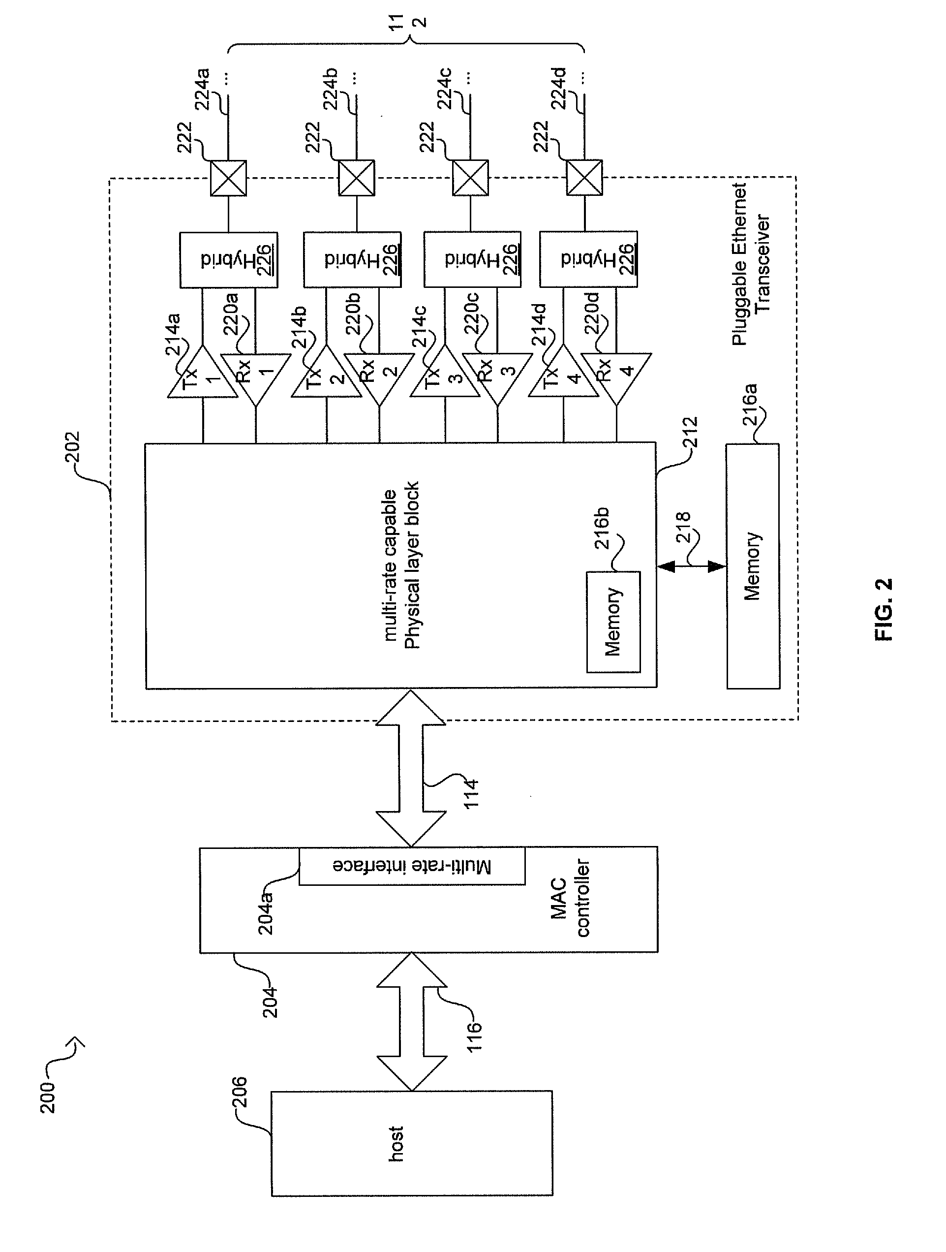
[0021]Certain embodiments of the invention can be found in a method and system for managing energy efficiency of a network link via pluggable transceiver modules in an energy efficient network device. An Ethernet network may comprise one or more link partners that may be coupled via an Ethernet link. The one or more link partners may comprise one or more pluggable PHY devices. The pluggable PHY devices and / or higher layer devices may be operable to determine one or more energy efficient network control policies that may specify a power level mode for the one or more link partners, and the one or more link partners may be configured to operate in the specified power level mode. In various embodiments of the invention, a power level mode of operation may be selected based on the energy efficient network control policies. Accordingly, one or more components of the pluggable PHY devices may be reconfigured based on the selected power level mode of operation. A first portion of the one o...


PUM


Abstract

An Ethernet network may comprise link partners that may be coupled via an Ethernet link. The link partners may comprise pluggable PHY devices. The pluggable PHY devices and / or other link partner devices may determine energy efficient network (EEN) control policies, may select a power level mode and may configure the link partners to operate in the power level mode. Some components may be reconfigured prior to sending an energy efficient network control signal to a link partner and configuring remaining components. Hardware, software and / or firmware may execute the pluggable PHY energy efficient network control policies. Packet data pending delivery may be buffered in the pluggable PHY. The pluggable PHY devices may comprise a MAC and / or a SERDES device. Exemplary form factors for the pluggable PHYs may comprise a SFP, a SFP+, a XENPAK, a X2, a XFP and / or a XPAK. Low power idle mode and / or sub-rate mode may be utilized.

Description

CROSS-REFERENCE TO RELATED APPLICATIONS / INCORPORATION BY REFERENCE[0001]This application makes reference to, claims priority to, and claims the benefit of U.S. Provisional Application Ser. No. 61 / 111,653, filed on Nov. 5, 2008.[0002]This application makes reference to:[0003]U.S. patent application Ser. No. 12 / 471,861 (Attorney Docket No. 20367US02) filed on May 26, 2009;[0004]U.S. patent application Ser. No. 12 / 470,785 (Attorney Docket No. 20368US02) filed on May 22, 2009;[0005]U.S. patent application Ser. No. 12 / 470,970 (Attorney Docket No. 20369US02) filed on May 22, 2009;[0006]U.S. patent application Ser. No. 11 / 685,554 (Attorney Docket No. 18031US01) filed Mar. 13, 2007; and[0007]U.S. patent application Ser. No. 11 / 473,205 (Attorney Docket No. 17396US02) filed Jun. 22, 2006.[0008]Each of the above stated applications is hereby incorporated herein by reference in its entirety.FIELD OF THE INVENTION[0009]Certain embodiments of the invention relate to networking. More specifically,...

Claims


Application Information

Patent Timeline
Patent Type & Authority Applications(United States)
IPC IPC(8): G06F1/00
CPCH04L12/12G06F1/3234Y02D30/32Y02D50/42Y02D30/30Y02D50/40Y02D30/00Y02D30/50
Inventor DIAB, WAEL WILLIAM
Owner AVAGO TECH WIRELESS IP SINGAPORE PTE
Learn More