Array antenna, radio communication apparatus, and array antenna control method

Inactive Publication Date: 2010-05-13
NEC CORP
View PDF8 Cites 13 Cited by
  • Summary
  • Abstract
  • Description
  • Claims
  • Application Information

AI Technical Summary

Benefits of technology

[0009]As mentioned above, the MINO method substantially improves communication performance in the multipath environment. However, in a line-of-sight environment, for example, where a high level signal comes from a certain direction, the effect of the MIMO method in improving communication performance is diminished.
[0010]Meanwhile, directional antennas that control the directivity towards the direction at which signals arrive are highly effective in improving communication performance in conditions where a high level signal comes from a certain direction. However, because the direction at which signals arrive is not defined as a single direction under the multipath environment, there are some cases in which directional antennas that control the directivity towards the direction at which signals arrive cannot achieve an effect equivalent to the MIMO method for improving communication performance.
[0012]An object of the present invention is therefore to provide an array antenna which can achieve good improvement in communication performance in varied environments such as a multipath environment, a line-of-sight environment, etc., a radio communication apparatus, and an array antenna control method.

Problems solved by technology

However, in a line-of-sight environment, for example, where a high level signal comes from a certain direction, the effect of the MIMO method in improving communication performance is diminished.
However, because the direction at which signals arrive is not defined as a single direction under the multipath environment, there are some cases in which directional antennas that control the directivity towards the direction at which signals arrive cannot achieve an effect equivalent to the MIMO method for improving communication performance.

Method used


Image

  • Array antenna, radio communication apparatus, and array antenna control method
  • Array antenna, radio communication apparatus, and array antenna control method
  • Array antenna, radio communication apparatus, and array antenna control method

Examples


Embodiment Construction

[0034]An exemplary embodiment of the present invention will be described in further detail with reference to the accompanying drawings.

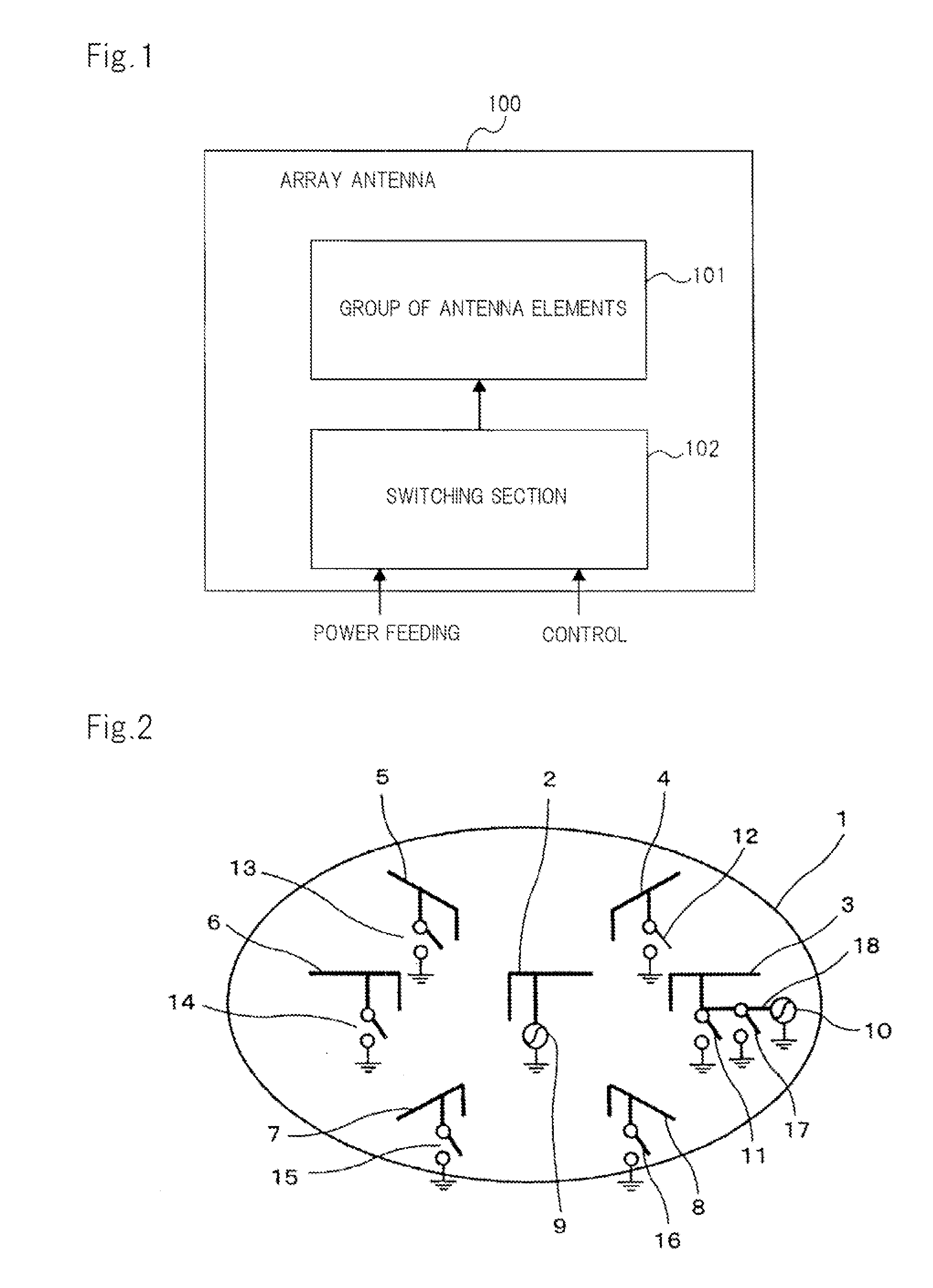
[0035]FIG. 1 is a block diagram showing a schematic configuration of an array antenna according to an exemplary embodiment of the present invention. Referring to FIG. 1, array antenna 100 includes group of antenna elements 101 and switching section 102.

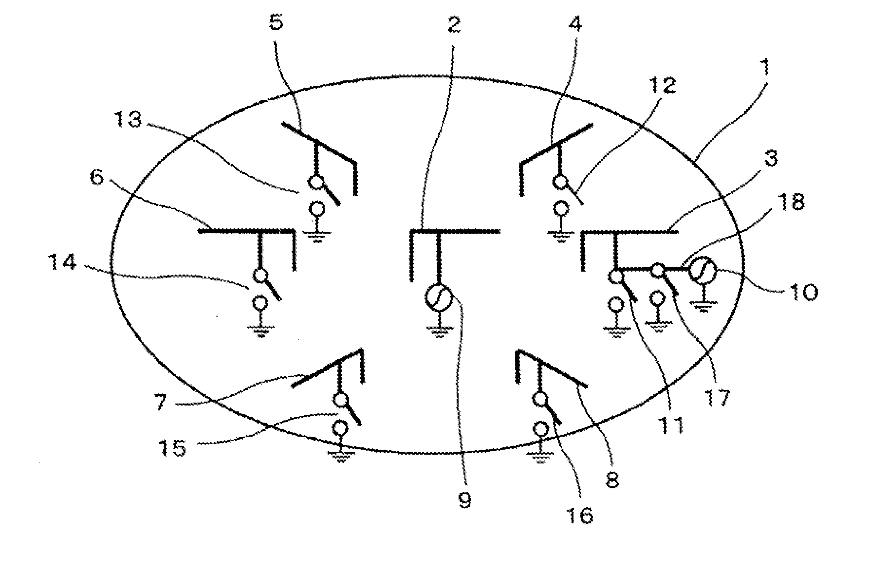
[0036]Group of antenna elements 101 has a plurality of antenna elements. Each antenna element included in group of antenna elements 101 offers individual control over the state of a feeding point.

[0037]Switching section 102 switches the feeding points of the antenna elements included in group of antenna elements 101 such that group of antenna elements 101 is operated either as an antenna for MIMO communication which transmits / receives a plurality of signals in parallel or as a directional array antenna which controls the directivity towards the direction at which the signals arrive.

[0038]When group of ...


PUM


Abstract

An array antenna includes a group of antenna elements and a switching section. The group of antenna elements has a configuration in which a plurality of antenna elements is arranged. The switching section has a plurality of switch elements capable of individually switching the feeding points of the antenna elements included in the group of antenna elements. By switching of the switch elements, the group of antenna elements is converted into an antenna for MIMO communication to transmit and receive a plurality of signals in parallel, or into a directional array antenna to control the directivity towards the direction at which the signals arrive.

Description

TECHNICAL FIELD[0001]The present invention relates to techniques of controlling an array antenna having a plurality of antenna elements.BACKGROUND ART[0002]Mobile communication terminal apparatus are required to communicate with base stations in many directions. The direction of a base station seen from a mobile communication terminal apparatus varies if the terminal apparatus moves. Because of that, a non-directional antenna is generally mounted on the mobile communication terminal apparatus. Non-directional antennas make it possible to have communications with the other party of any direction, but, in general, they underperform on communications in a direction towards which the directivity of directional antennas are turned. Recently, there has been a demand for improvement in communication performance, and techniques for that were developed and are now put to practical use.[0003]For example, there is a technique of improving communication performance by controlling the directivit...

Claims


Application Information

Patent Timeline
IPC IPC(8): H01Q3/24
CPCH01Q3/446H01Q9/0421H04B7/0871H01Q21/28H04B7/0689H01Q9/42
Inventor FUKUDA, JUNICHI
Owner NEC CORP
Why Eureka
Try Eureka