Apparatus and method for improving image-sticking effect of liquid crystal display

Inactive Publication Date: 2006-01-12
CHUNGHWA PICTURE TUBES LTD
View PDF3 Cites 27 Cited by
  • Summary
  • Abstract
  • Description
  • Claims
  • Application Information

AI Technical Summary

Benefits of technology

[0004] It is the objective of the present invention to provide a method and an apparatus for improving the image-sticking effect of a liquid crystal display resulting from a still image appearing on a panel of the liquid crystal display for a period of time.
[0005] According to the aforementioned objective of the present invention, an apparatus for improving the image-sticking effect of a liquid crystal display is provided. The apparatus recognizes the state of an image displayed on a panel of the liquid crystal display and then forces image to vary when detecting a still image state.
[0006] According to the aforementioned objective of the present invention, on the other hand, a method for improving the image-sticking effect of a liquid crystal display is provided. The image-sticking effect caused by DC charges is diminished through altering an image displayed on a panel, especially when the displayed image is still on the panel for a long period of time.
[0007] In accordance with a preferred embodiment of the present invention, a comparator first analyzes an image datum and determines whether it's a still image or not after receiving it. If a still image is detected, a value of a counter is then increased. An inset image is next produced by an inset device and is transmitted to a panel of a liquid crystal display when the value of the counter successively accumulates to a threshold value. Therefore, a still image appearing on the panel of the liquid crystal display is changed by displaying the inset image, so as to reduce the image-sticking effect of the liquid crystal display.

Problems solved by technology

The image-sticking effect caused by DC charges is diminished through altering an image displayed on a panel, especially when the displayed image is still on the panel for a long period of time.

Method used


Image

  • Apparatus and method for improving image-sticking effect of liquid crystal display
  • Apparatus and method for improving image-sticking effect of liquid crystal display
  • Apparatus and method for improving image-sticking effect of liquid crystal display

Examples


Embodiment Construction

[0012] A preferred embodiment in accordance with the present invention is disclosed in details as follows, taken in conjunction with the accompanying drawings.

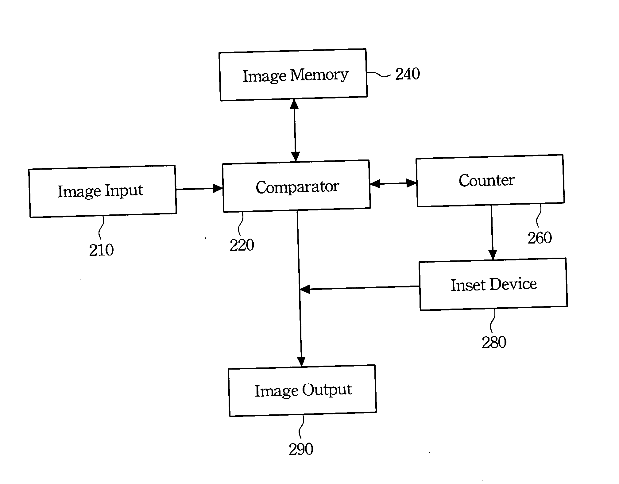
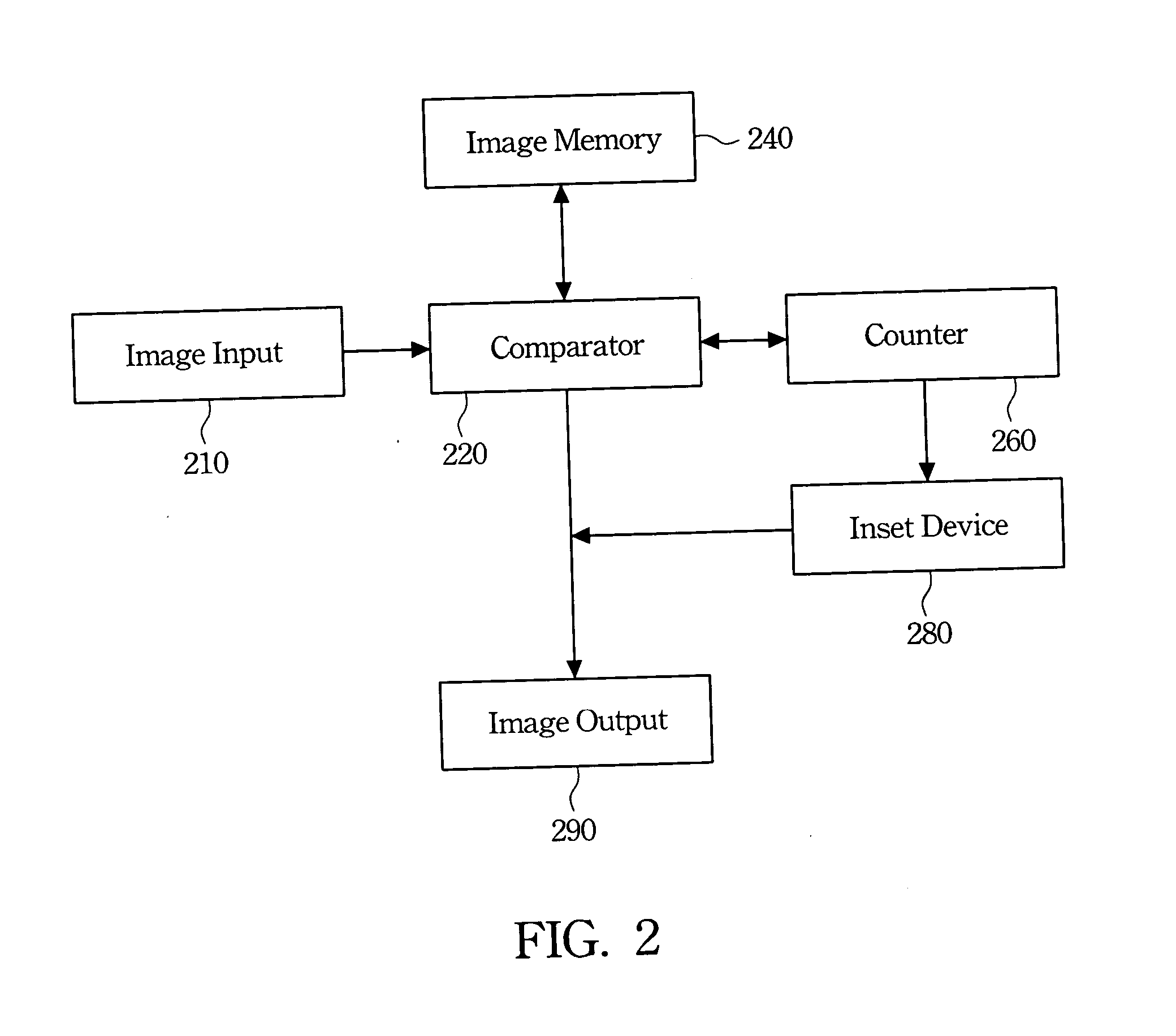
[0013]FIG. 2 shows a block diagram of an apparatus for improving the image-sticking effect of a liquid crystal display in accordance with the preferred embodiment of the present invention. As illustrated in FIG. 2, at least an image datum is transmitted by an image input device 210 continuously to a comparator 220 and is then stored in a storage, like an image memory 240. Further, the image datum represents a series of image signals transmitted therein in every frame time in the preferred embodiment. When receiving the image datum, the comparator 220 compares the image datum with a previous image datum stored in the image memory 240 first by analyzing image signals thereof between each other. As a proportion of image signals varies, for example, up to 80% of image signals of the image datum differ from those of the previous i...


PUM


Abstract

An apparatus for improving an image-sticking effect of a liquid crystal display is described. The apparatus has a comparator, a counter connected to the comparator, and an inset device connected to the counter. When receiving an image datum, the comparator first compares the image datum with a previous image datum stored in an image memory to determine whether the image datum is a still image or not. If the image datum is not a still image, the image datum is directly transmitted to an image output device. On the contrary, if the image datum is a still image, a value of the counter is then increased. An inset image is produced by the inset device and is transmitted to the image output device when the value equals a threshold value. As a result, the image-sticking effect is reduced because an image that is still for a long period is forced to change.

Description

FIELD OF THE INVENTION [0001] The present invention relates to a method and an apparatus for improving the image-sticking effect of a display, and more particularly, to a method and an apparatus for improving the image-sticking effect of a liquid crystal display. BACKGROUND OF THE INVENTION [0002] Opto-electronics technologies have recently progressed by leaps and bounds due to the coming of the digital era, which also has stimulated the market for liquid crystal displays (LCDs). The liquid crystal displays possess many advantages, such as, for example, high display quality, small volume occupation, light weight, low driving voltage, and low power consumption. Therefore, the liquid crystal displays are gradually replacing conventional cathode ray tube (CRT) displays and are applied widely to 3C (computers, communications, and consumer electronic) products, for example, personal digital assistants (PDAs), cellular phones, video recording units, notebook computers, desktop monitors, v...

Claims


Application Information

Patent Timeline
IPC IPC(8): G09G3/36
CPCG09G3/36G09G2320/103G09G2320/0257G09G2310/061
Inventor YEH, LIANG-HUA
Owner CHUNGHWA PICTURE TUBES LTD
Why Eureka
Try Eureka