Backlighting system for a 2d/3d autostereoscopic multiview display

a multi-view display and backlighting technology, applied in optics, instruments, electrical equipment, etc., can solve the problem of all loss of resolution in 3d mode in the horizontal direction

Active Publication Date: 2010-05-13
DIMENSION TECH
View PDF9 Cites 63 Cited by
  • Summary
  • Abstract
  • Description
  • Claims
  • Application Information

AI Technical Summary

Benefits of technology

[0015]The backlight system of the invention creates illumination behind a liquid crystal or other transparent display. In a 3D mode of operation it produces a series of precise, thin slanted lines with dark space in between which are used to make multiple perspective views, displayed simu

Problems solved by technology

Furthermore, the resolution lost in 3D mod

Method used


Image

  • Backlighting system for a 2d/3d autostereoscopic multiview display
  • Backlighting system for a 2d/3d autostereoscopic multiview display
  • Backlighting system for a 2d/3d autostereoscopic multiview display

Examples


Embodiment Construction

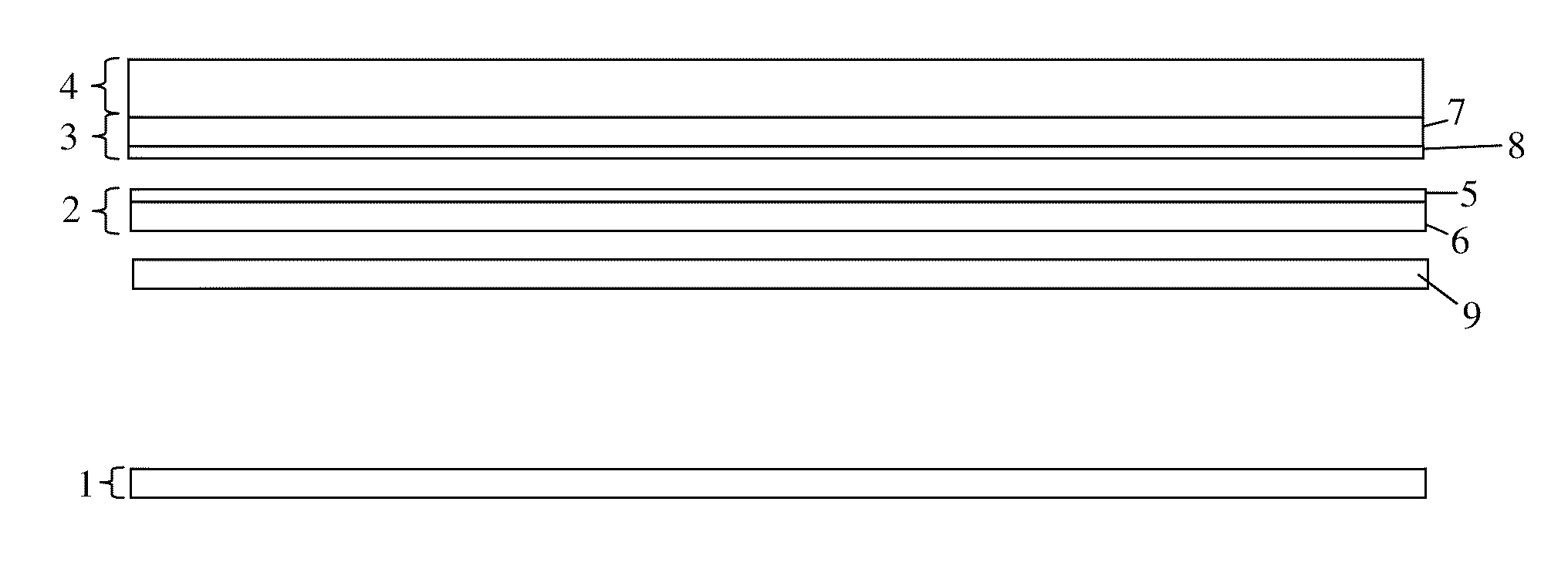
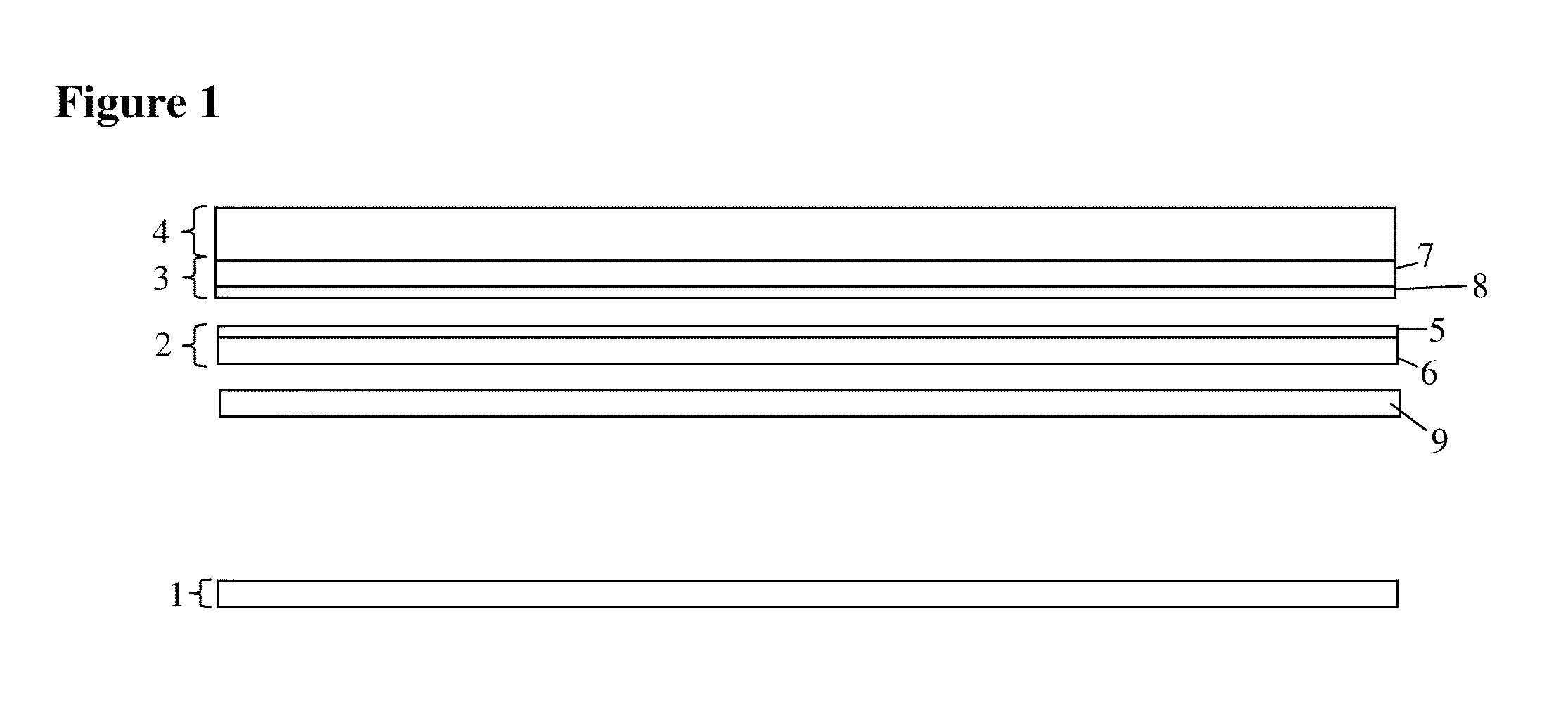
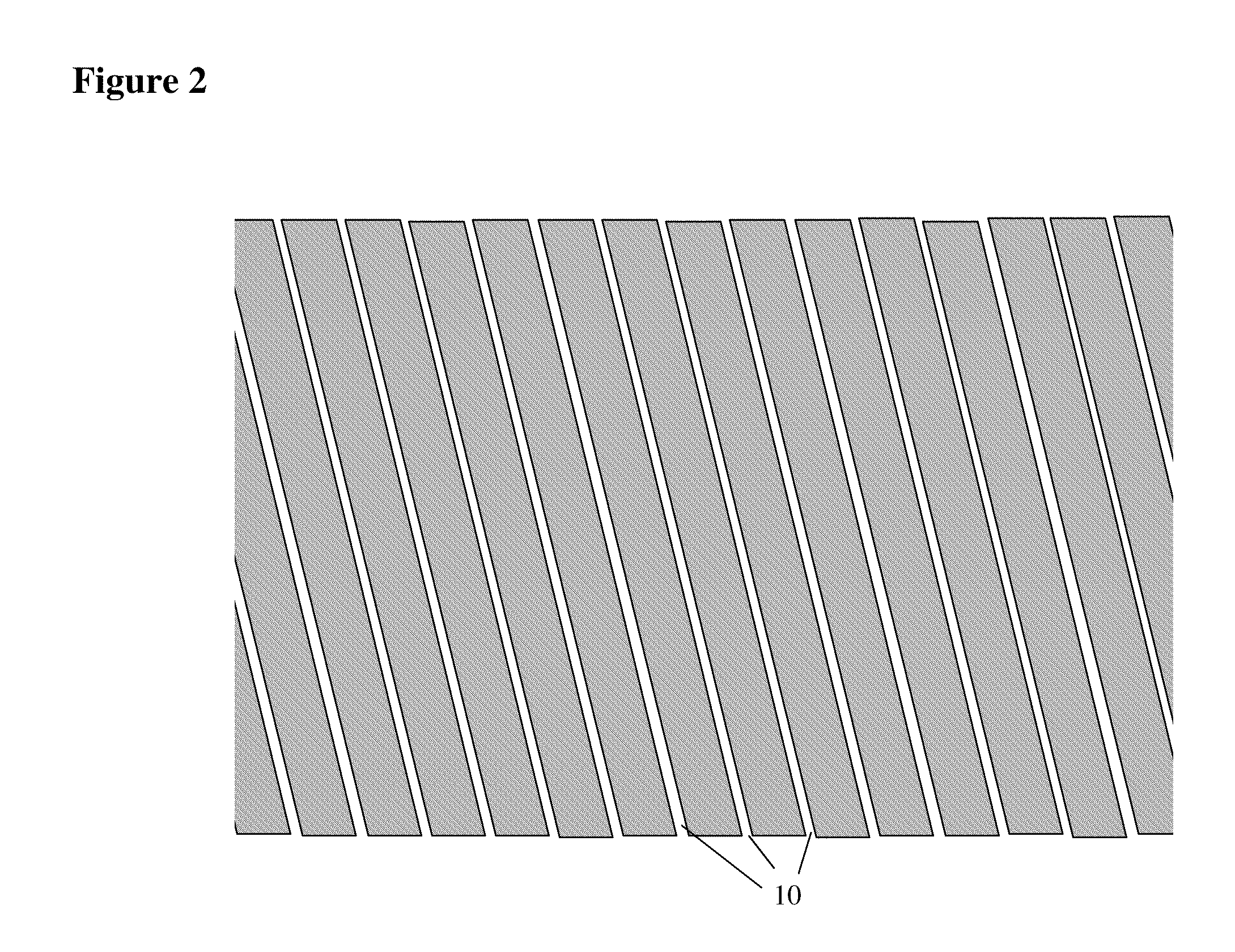
[0039]The backlight of the invention produces the effect of producing multiview autostereoscopic image whose resolution loss is divided between the horizontal and vertical directions by generating light emitting lines behind the LCD that are tilted at a 3:1 slope angle, in other words at an angle of 18.435 degrees to the vertical. The light lines are situated behind the pixels of the LCD, on which are displayed image information from N different perspective view images on diagonal lines of pixel elements like those shown in FIGS. 10a-10b (which is described in more detail below).

[0040]The light emitting lines are produced by means of a light source that emits light from large lines of light sources tilted at a 3:1 slope angle (18.435 degrees from the vertical) in combination with a lenticular lens whose lenslets run parallel to the light emitting lines, and produces many small images of each light emitting source, plus a separate diffuser component that scatters light to produce eve...


PUM


Abstract

The backlight system of the invention creates illumination behind a liquid crystal or other transparent display. In one mode of operation it produces a series of precise, thin slanted lines with dark space in between which are used to make multiple perspective views, displayed simultaneously on the LCD, visible from a series of horizontally spaced viewing zones spaced in front of the display. In another mode of operation, it produces even diffuse illumination similar to that generated by conventional backlights, allowing the LCD to display conventional 2D images.

Description

REFERENCE TO RELATED APPLICATIONS[0001]This application claims one or more inventions which were disclosed in Provisional Application No. 60 / 112,424, filed Nov. 7, 2008, entitled “BACKLIGHTING SYSTEM FOR A 2D / 3D AUTOSTEREOSCOPIC MULTIVIEW DISPLAY”. The benefit under 35 USC §119(e) of the United States provisional application is hereby claimed, and the aforementioned application is hereby incorporated herein by reference.BACKGROUND OF THE INVENTION[0002]1. Field of the Invention[0003]The invention pertains to the field of backlights for displays. More particularly, the invention pertains to backlight systems for liquid crystal (LCD) or other displays.[0004]2. Description of Related Art[0005]U.S. Pat. No. 5,410,345 “Stroboscopic Illumination System for Video Displays” discloses a backlighting system for video displays. It uses a number of vertically oriented parallel light sources (such as fluorescent tubes) spaced behind a lenticular lens, which creates up to hundreds of images of th...

Claims


Application Information

Patent Timeline
IPC IPC(8): G02F1/13357G02F1/1335G02B30/33
CPCG02B27/2214G09G3/003G09G3/3426G09G3/3611G09G2300/023H04N13/0418G09G2310/024G09G2320/068G09G2354/00H04N13/0411H04N13/0415G09G2310/0237H04N13/32H04N13/312H04N13/317G02B30/33G02B30/27
Inventor EICHENLAUB, JESSE B.
Owner DIMENSION TECH
Why Eureka
Try Eureka