
Three-dimensional space scanner

Inactive Publication Date: 2010-05-13
SAMSUNG ELECTRO MECHANICS CO LTD
View PDF1 Cites 9 Cited by
  • Summary
  • Abstract
  • Description
  • Claims
  • Application Information

AI Technical Summary

Benefits of technology

[0009]An aspect of the present invention is to provide a three-dimensional space scanner, which scans a mobile object in a horizontal as well as vertical direction so as to detect a distance from a surrounding obstacle, thereby obtaining spatial data.
[0024]According to the present invention, the three-dimensional space scanner can rotate and tilt the reflecting mirror so as to three-dimensionally scan a mobile object in a horizontal as well as vertical direction using a laser beam, thereby detecting a distance from a surrounding obstacle to obtain three-dimensional spatial data.

Problems solved by technology

That is, sensible objects are limited to those onto which the laser beams are emitted and to those which are located at the same horizontal plane of the laser emitter.
Thus, it is impossible to scan other ranges and distance information on only a specific horizontal plane can be obtained.
However, while consumer demands on autonomous mobile devices capable of performing more accurate drive and more various operations are increasing, the distance information only on a specific horizontal plane cannot sufficiently ensure safety and functionality.

Method used


Image

  • Three-dimensional space scanner
  • Three-dimensional space scanner
  • Three-dimensional space scanner

Examples


first embodiment

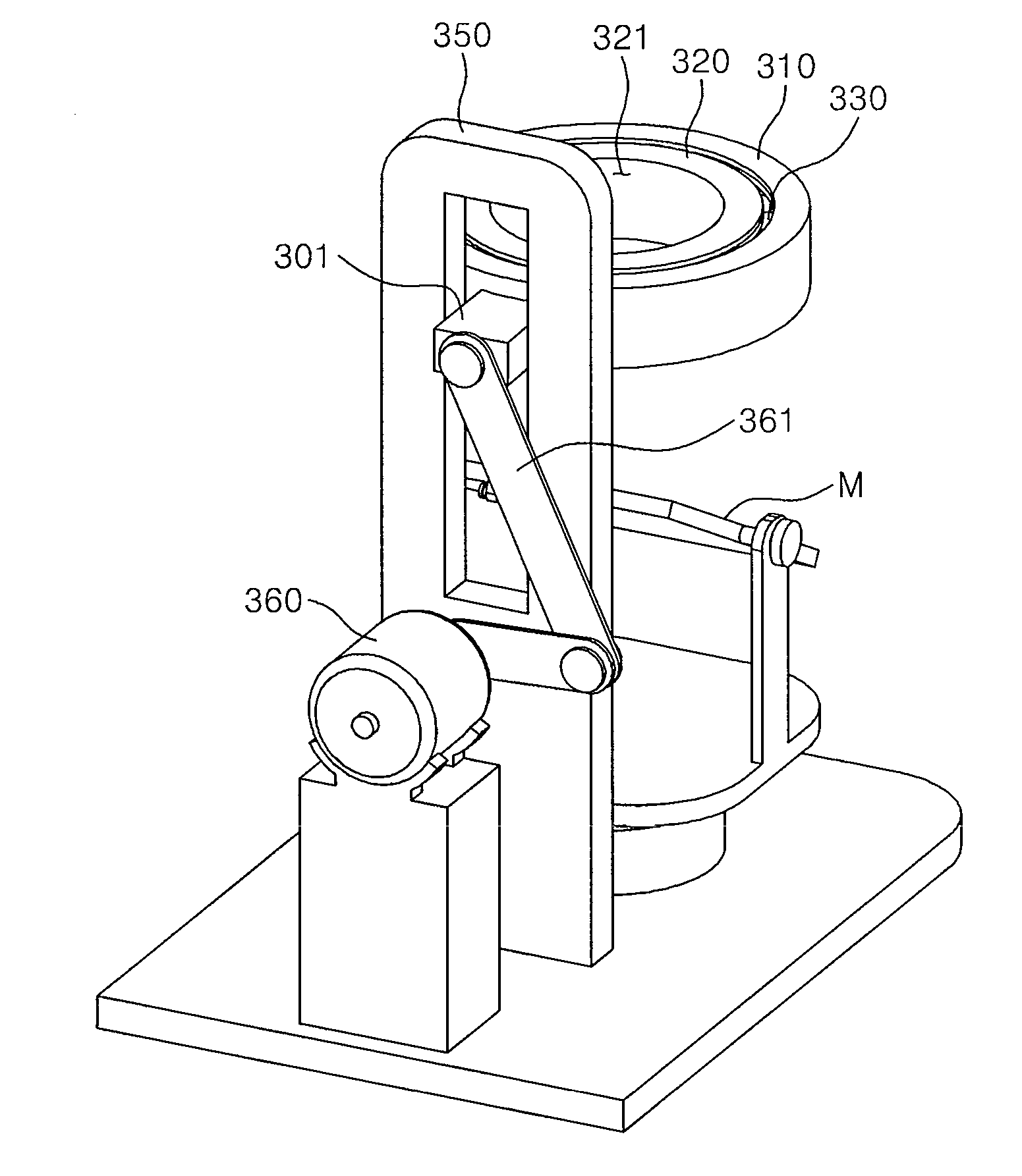
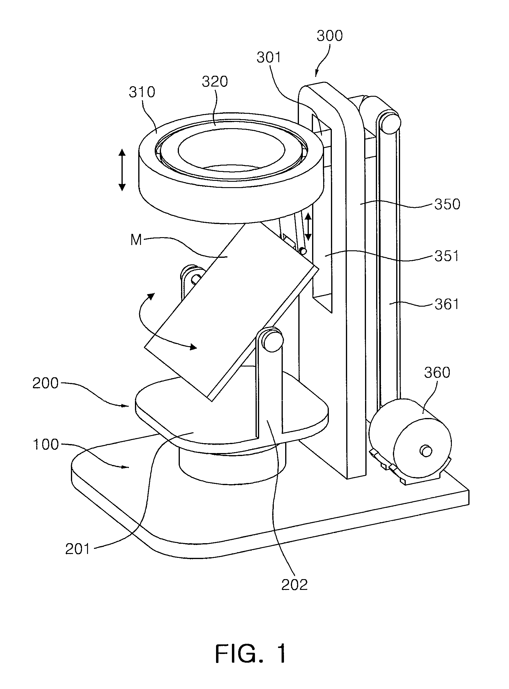
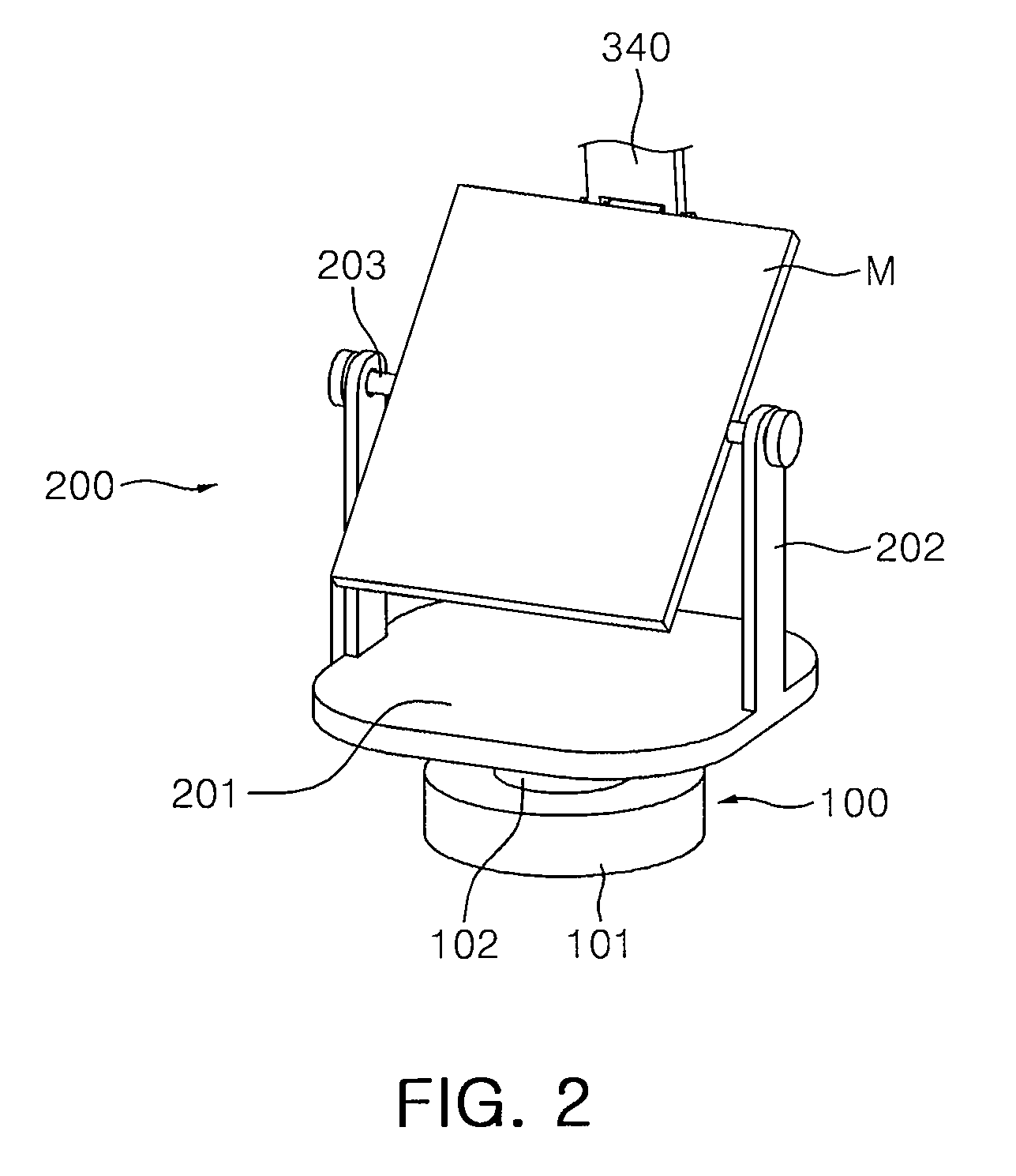
[0036]FIG. 1 is a perspective view illustrating a three-dimensional space scanner according to the present invention. FIG. 2 is a perspective view illustrating a rotating drive and a mirror holder for the three-dimensional space scanner illustrated in FIG. 1. FIGS. 3A and 3B are perspective views illustrating a tilting drive for the three-dimensional space scanner illustrated in FIG. 1.

[0037]As illustrated in FIG. 1, the three-dimensional space scanner according to a first embodiment of the present invention includes a rotating drive 100, a mirror holder 200, and a tilting drive 300.

[0038]In the three-dimensional space scanner, the rotating drive 100 is for generating a rotating force for continuously rotating a reflecting mirror M at an angle of 360° in a horizontal direction, and is provided with a rotating motor 101 on a lower side thereof which rotates a vertical rotating shaft 102 when powered. The rotating motor 101 can be installed in a case for protection.

[0039]The vertical ...

second embodiment

[0068]FIG. 6 is a perspective view illustrating a three-dimensional space scanner according to the present invention.

[0069]The three-dimensional space scanner according to a second embodiment of the present invention as illustrated in FIG. 6 is substantially the same configuration as that according to a embodiment of the present invention as illustrated in FIGS. 1 through 5C.

[0070]However, in conjunction with detailed configuration of the tilting drive, the second embodiment of the present invention as illustrated in FIGS. 6 through 8C is different from the first embodiment of the present invention as illustrated in FIGS. 1 through 5C. Therefore, the following description will be mainly made of the configuration and operation of the tilting drive but a description of the same parts will be omitted.

[0071]As illustrated in FIG. 6, the three-dimensional space scanner according to a second embodiment of the present invention includes a rotating drive 100, a mirror holder 200, a cam 400,...


PUM


Abstract

A three-dimensional space scanner is configured so that a reflecting mirror is rotated and tilted so as to scan a mobile object in a horizontal as well as vertical direction, thereby obtaining spatial data.

Description

CROSS-REFERENCE TO RELATED APPLICATIONS[0001]This application claims the priority of Korean Patent Application No. 2008-0111888, filed on Nov. 11, 2008, in the Korean Intellectual Property Office, the disclosure of which is incorporated herein by reference.BACKGROUND OF THE INVENTION1. Field of the Invention[0002]The present invention relates to a three-dimensional space scanner, and more particularly, to a three-dimensional space scanner, in which a reflecting mirror is rotated and tilted so as to scan a mobile object in a horizontal as well as vertical direction, thereby obtaining spatial data.[0003]2. Description of the Related Art[0004]An autonomous mobile (walking) device such as a mobile robot senses a surrounding object and measures a distance from the object using a laser beam, supersonic waves or the like in order to locate its position and determine a moving direction.[0005]Laser range finding is known as a most accurate method for measuring the distance to an object, part...

Claims


Application Information

Patent Timeline
IPC IPC(8): G02B26/10
CPCG02B26/101B25J13/08B25J19/04
Inventor LEE, BACK KUEPARK, GIL HANKIM, HONG-KIRAA, KWANG YOUEL
Owner SAMSUNG ELECTRO MECHANICS CO LTD
Learn More