Differential timing transfer over synchronous ethernet using digital frequency generators and control word signaling

a technology of digital frequency generators and signaling, applied in the direction of synchronisation receivers, automatic control, instruments, etc., can solve the problems of inability to guarantee the performance of acr techniques, packet network impairments,

Inactive Publication Date: 2010-05-13
RPX CLEARINGHOUSE
View PDF8 Cites 60 Cited by
  • Summary
  • Abstract
  • Description
  • Claims
  • Application Information

AI Technical Summary

Benefits of technology

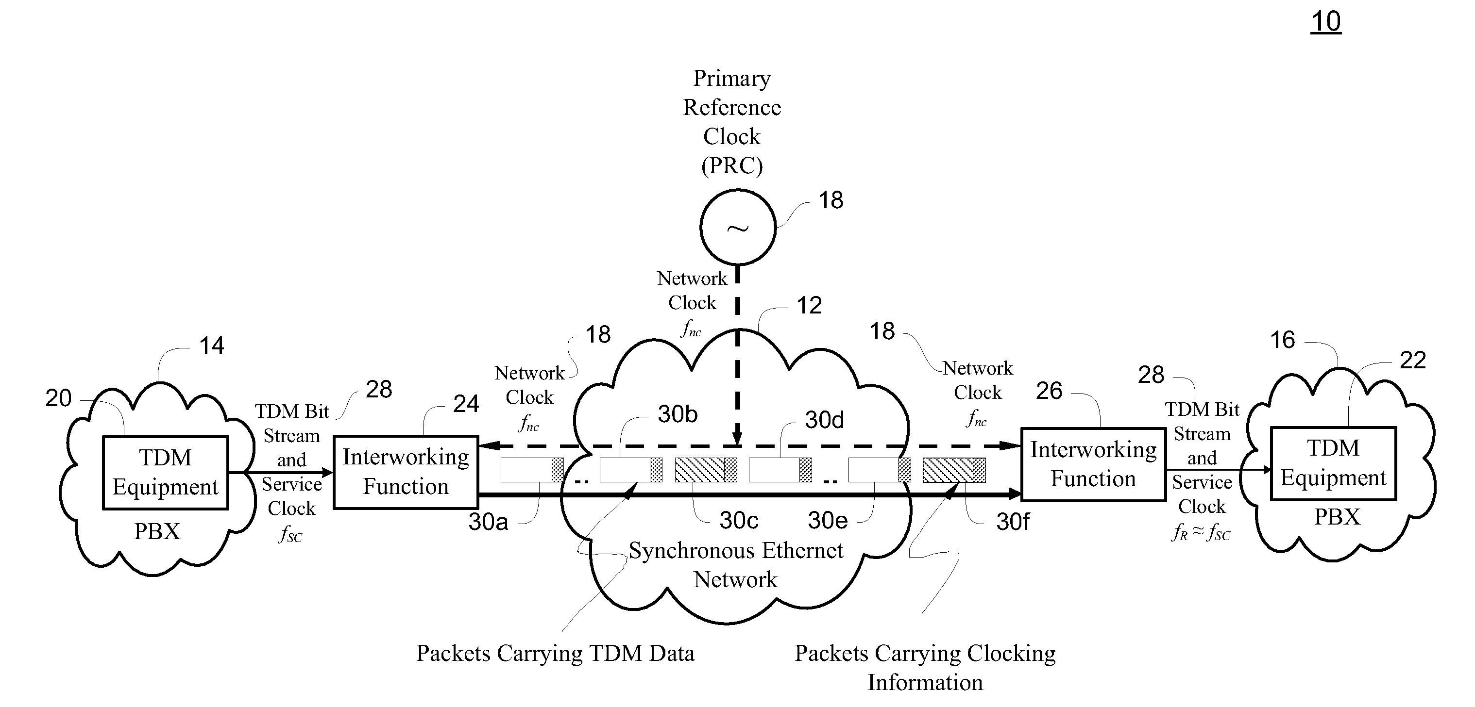
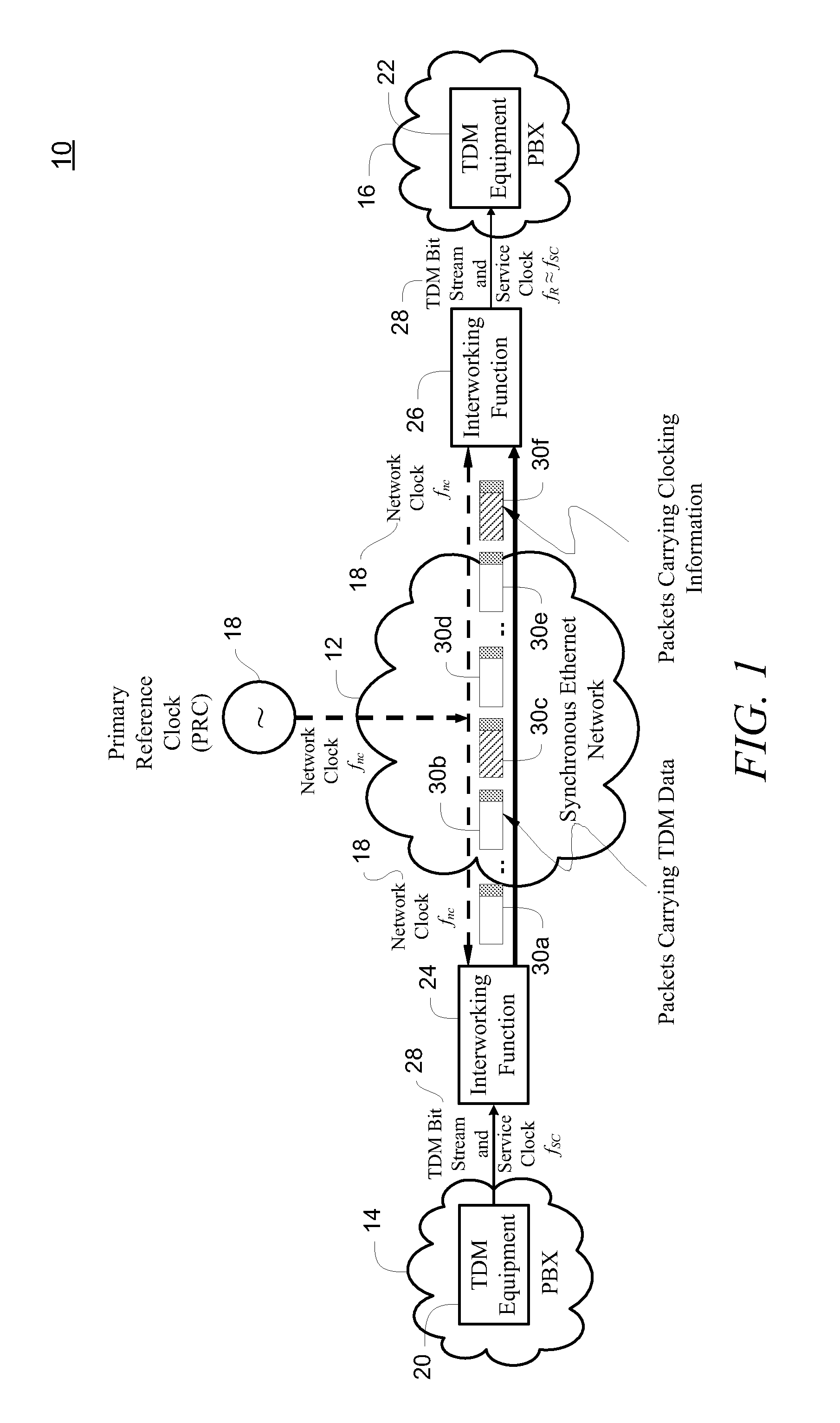
[0009]The present invention advantageously provides a method, system and master service interface for transferring differential timing over a packet network. Generally, the master service interface creates a control signal that is used to synthesize a copy of a service clock connected to the master service interface, as well as to recover or recreate the service clock at a remote receiving, or “slave” service interface.
[0010]In accordance with one aspect of the present invention, a method is provided for transferring differential timing over a packet network. The packet network includes a service clock connected to a transmitting service interface, which in turn is coupled to a receiving service interface through a network backplane. A primary reference clock is provided to time the network backplane. The primary reference clock is used to synthesize a copy of the service clock connected to the transmitting service interface. A first control word is generated which contains an error differential between the service clock and the synthesized copy of the service clock. A packet containing the first control word is transmitted through the network backplane to the receiving service interface. The first control word is used to recreate the service clock for timing the receiving service interface.
[0011]In accordance with another aspect of the present invention, a system for transferring differential timing over a packet network includes a network backplane, a transmitting service interface, and a rece

Problems solved by technology

In adaptive clock recovery, because there is no network-wide reference clock available, the pe

Method used


Image

  • Differential timing transfer over synchronous ethernet using digital frequency generators and control word signaling
  • Differential timing transfer over synchronous ethernet using digital frequency generators and control word signaling
  • Differential timing transfer over synchronous ethernet using digital frequency generators and control word signaling

Examples


Embodiment Construction

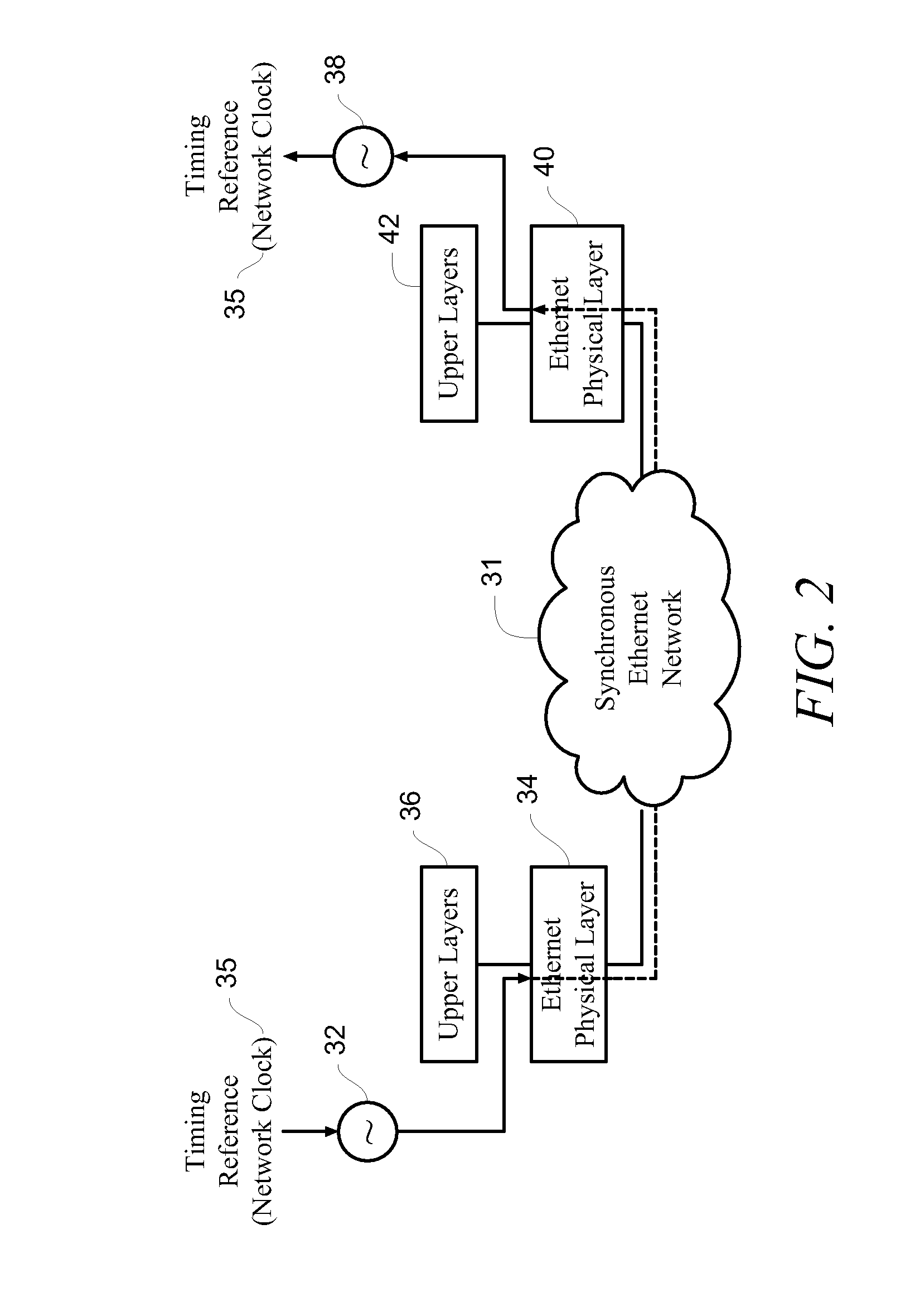
[0037]Before describing in detail exemplary embodiments that are in accordance with the present invention, it is noted that the embodiments reside primarily in combinations of apparatus components and processing steps related to implementing a system and method for providing differential timing transfer over a Synchronous Ethernet network. Accordingly, the system and method components have been represented where appropriate by conventional symbols in the drawings, showing only those specific details that are pertinent to understanding the embodiments of the present invention so as not to obscure the disclosure with details that will be readily apparent to those of ordinary skill in the art having the benefit of the description herein.

[0038]As used herein, relational terms, such as “first” and “second,”“top” and “bottom,” and the like, may be used solely to distinguish one entity or element from another entity or element without necessarily requiring or implying any physical or logic...


PUM


Abstract

A method, system and master service interface transfer differential timing over a packet network. The transmitting service interface receives a service clock and is coupled to a receiving service interface through a network backplane. A primary reference clock is provided to time the network backplane. The primary reference clock and the service clock are used to synthesize a copy of the service clock connected to the transmitting service interface. A first control word containing an error differential between the service clock and the synthesized copy of the service clock is generated and transmitted through the network backplane via a packet. The first control word, together with the primary reference clock, is used to recreate the service clock for timing the receiving service interface.

Description

CROSS-REFERENCE TO RELATED APPLICATION[0001]n / aSTATEMENT REGARDING FEDERALLY SPONSORED RESEARCH OR DEVELOPMENT[0002]n / aFIELD OF THE INVENTION[0003]The present invention relates generally to a method and system for differential timing transfer in communication networks and more specifically to a method and system for differential timing transfer over Synchronous Ethernet using digital frequency generators and control word signaling.BACKGROUND OF THE INVENTION[0004]Differential timing transfer is used when there is a network interface with its own source clock and there is the need to transfer this clock over a core packet network (with its own independent network-wide reference clock) to another interface. This transfer is performed while each interface and the core network maintain their timing traceability to their independent source clocks.[0005]Differential clocking, such as the Synchronous Residual Time Stamp (“SRTS”) method specified for Asynchronous Transfer Mode (“ATM”) netwo...

Claims


Application Information

Patent Timeline
IPC IPC(8): H04J3/06
CPCG06F1/0328H03L7/0805H03L7/085H04L7/0079H03L2207/50H04J3/0632H04J3/0658H03L7/089
Inventor AWEYA, JAMESOUELLETTE, MICHELMONTUNO, DELFIN Y.
Owner RPX CLEARINGHOUSE
Why Eureka
Try Eureka