Robot system, robot control device and method for controlling robot

a robot and control device technology, applied in the field of robot systems and robot control devices, can solve the problems of high cost or labor, degrade the reliability or accuracy of the information output of the acceleration sensor, etc., and achieve the effect of facilitating acquisition and reducing blurring

Inactive Publication Date: 2010-05-13
SEIKO EPSON CORP
View PDF7 Cites 23 Cited by
  • Summary
  • Abstract
  • Description
  • Claims
  • Application Information

AI Technical Summary

Benefits of technology

[0020]With the above method, the locus image of the moved reference mark is extracted from the captured blurred image obtained by capturing the target object together with the reference mark during movement of the movable section. While making the extracted locus image to be the point spread function, an image whose blurring is reduced, is restored from the captured blurred image by the image transformation by using the point spread function. A position of the target object as a moving destination of

Problems solved by technology

However, since the acceleration sensor is provided on the movable section of the robot for industrial use, fluctuation in temperature or variation in acceleration may be increased depending on a working environment or work so that reliability or accuracy of the information output

Method used


Image

  • Robot system, robot control device and method for controlling robot
  • Robot system, robot control device and method for controlling robot
  • Robot system, robot control device and method for controlling robot

Examples


first embodiment

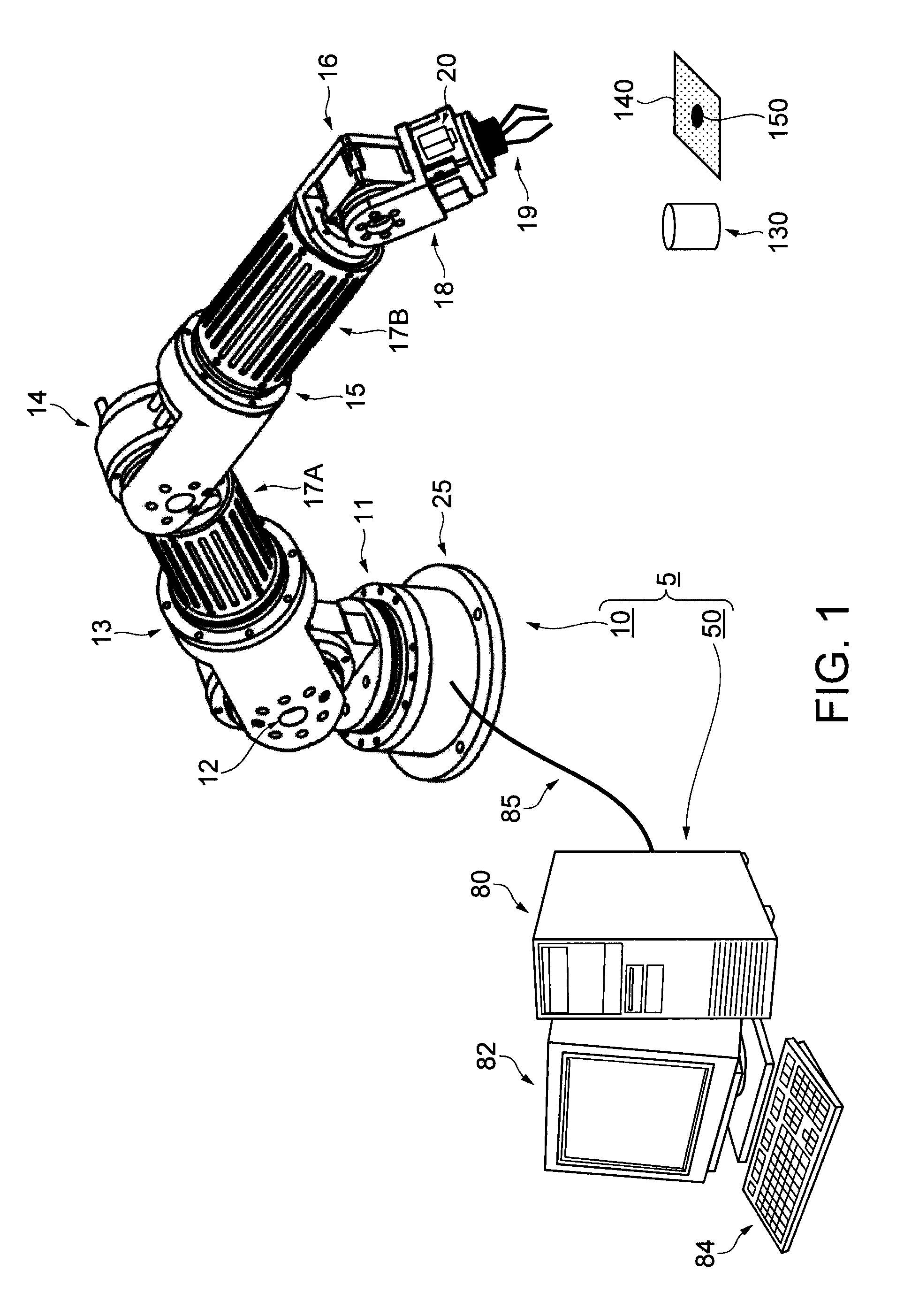
[0029]FIG. 1 is a schematic view showing a robot system 5 according to a first embodiment of the invention. The robot system 5 is equipped with a robot 10 and a robot control device 50 that controls the robot 10. The robot 10 is a six-axis control multi-joint type robot that has movable sections including a robot base 25 as a base body to be placed on a placement face, a first shaft 11 that rotates around a vertical axis with respect to the placement face, a second shaft 12 that turns an arm 17A about a horizontal axis, a third shaft 13 that rotates in an axial direction of the arm 17A, a fourth shaft 14 that is fixed to the arm 17A and turns an arm 17B in a horizontal direction, a fifth shaft 15 that rotates in an axial direction of the arm 17B, and a sixth shaft 16 that is fixed to the arm 17B and turns a wrist 18 in the horizontal direction. A hand 19 for gripping a component and a digital camera 20 as an image capture unit for capturing in a gripping direction of the hand 19 by ...

second embodiment

[0042]A second embodiment of the invention will be described with reference to FIGS. 5A and 5B. Note that, the sections, portions or members the same as in the above described first embodiment are denoted by the same numerals, and their descriptions are omitted. In the first embodiment, the workpiece 130 and one marker 140 are disposed in the view field of the digital camera 20. However, in the second embodiment, the workpiece 130 and four markers 140 whose positional relationships are already known are placed on an identical plane of the workpiece 130 at a peripheral portion of the workpiece 130 as shown in FIG. 5A. Note that, it is enough to put at least three markers 140 in the identical view field of the digital camera 20.

[0043]FIG. 5B is an explanatory view showing an image captured when the arm 17 moves straight. While the image of the marker 140 is actually blurred in the moving direction, the blurring of the marker 140 is not indicated because its blurring is not essential f...


PUM


Abstract

A robot system includes a robot having a movable section, an image capture unit provided on the movable section, an output unit that allows the image capture unit to capture a target object and a reference mark and outputs a captured image in which the reference mark is imaged as a locus image, an extraction unit that extracts the locus image from the captured image, an image acquisition unit that performs image transformation on the basis of the extracted locus image by using the point spread function so as to acquire an image after the transformation from the captured image, a computation unit that computes a position of the target object on the basis of the acquired image, and a control unit that controls the robot so as to move the movable section toward the target object in accordance with the computed position.

Description

BACKGROUND[0001]1. Technical Field[0002]The present invention relates to a robot system, a robot control device and a method for controlling a robot.[0003]2. Related Art[0004]Multi-axis control robots for industrial use have been used in factories or manufacturing sites for automation or labor-saving. Such a robot for industrial use has a digital camera functioning as eyes of a human. The robot can autonomously move to a position where it can grip a target object by performing image-processing of images captured during movement and can autonomously pass over an obstacle during the movement. In recent years, particularly, it has been necessary to enhance accuracy in positioning by means of a high resolution digital camera and to perform correction of blurring in a captured image so as to deal with a high speed operation by the robot for industrial use. In a blur correction method as described above, information about movement of a moving object is detected by means of an acceleration...

Claims


Application Information

Patent Timeline
IPC IPC(8): G06T7/00
CPCG06T2207/30204G06T2207/30164G06T5/003
Inventor INAZUMI, MITSUHIRO
Owner SEIKO EPSON CORP
Why Eureka
Try Eureka