
Endoscopic cutting and debriding device mounted on a flexible and maneuverable tube employing a fluid-driven turbine

Inactive Publication Date: 2010-05-13
RONTAL MICHAEL
View PDF36 Cites 45 Cited by
  • Summary
  • Abstract
  • Description
  • Claims
  • Application Information

AI Technical Summary

Benefits of technology

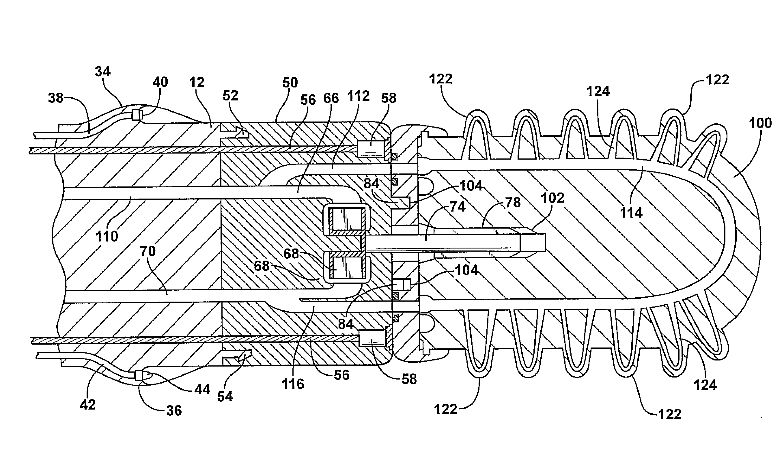
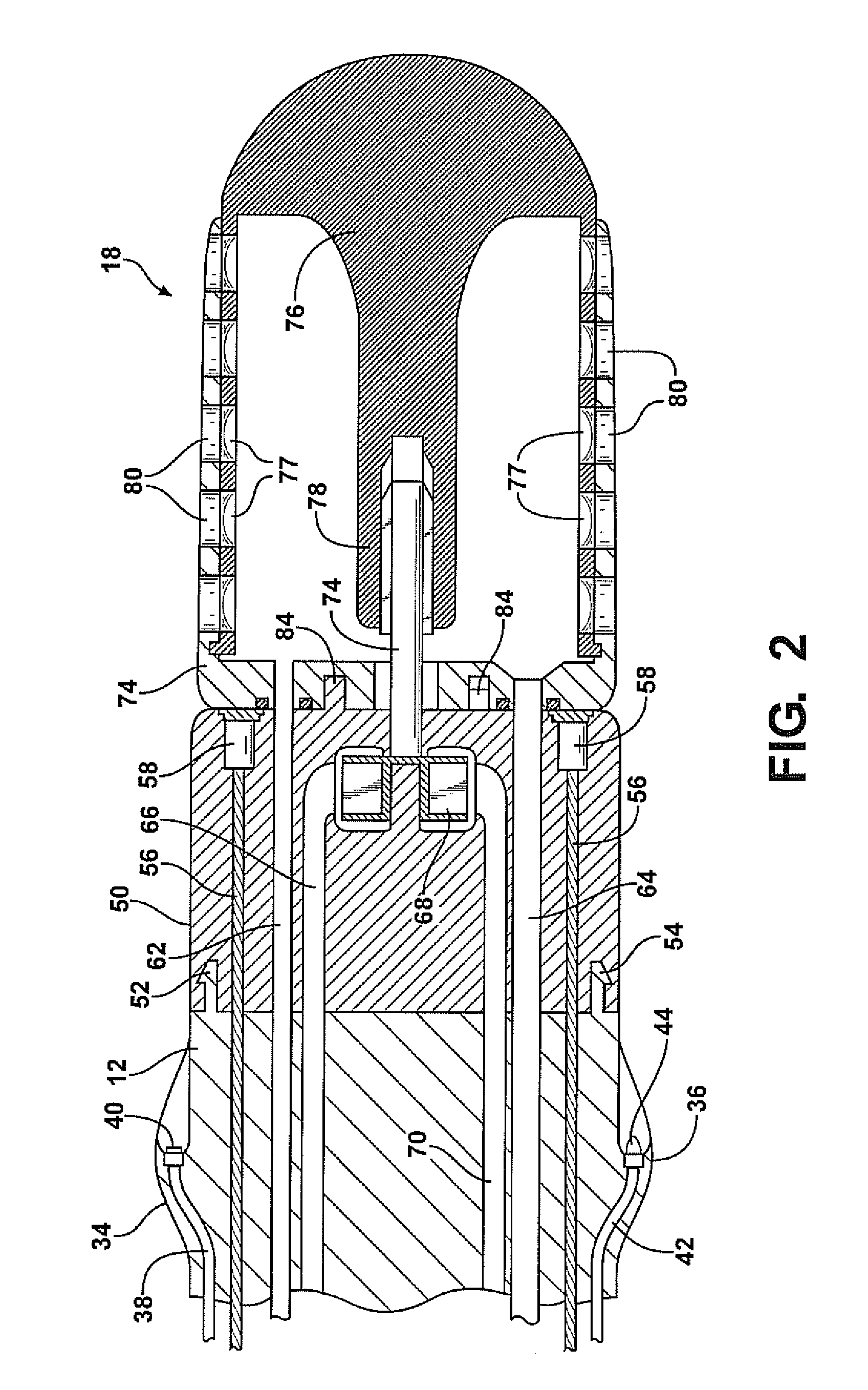
[0008]In a preferred embodiment of the invention, which will be subsequently disclosed in detail, the turbine shaft powers the operating surgical instruments through a detachable connection which allows different surgical tools to be connected to the endoscope. For example, a debrider of the type employing an interior cutting tube mounted within an outer cutter housing may be used to remove soft tissue. The inner cutter member may be hollow and connected to a source of suction introduced from the proximal end, which passes through a second lumen in the endoscope. The fluid which turns the turbine may also be used to cool the surgical cutter or bathe the surgical area, with biofilm reducing agents or the like.
[0009]In a preferred embo

Problems solved by technology

The passage of electric currents through the endoscope always creates the possibility of accidental introduction of the electrical currents to the area of the surgical site.
However, when rotary powered surgical instruments such as mills, grinders, or debriders must be powered, either electrical currents must be introduced to the distal end through the endoscope to power electric motors or rather cumbersome rotary shafts must carry power from the proximal to the distal ends of the device.

Method used


Image

  • Endoscopic cutting and debriding device mounted on a flexible and maneuverable tube employing a fluid-driven turbine
  • Endoscopic cutting and debriding device mounted on a flexible and maneuverable tube employing a fluid-driven turbine
  • Endoscopic cutting and debriding device mounted on a flexible and maneuverable tube employing a fluid-driven turbine

Examples


Embodiment Construction

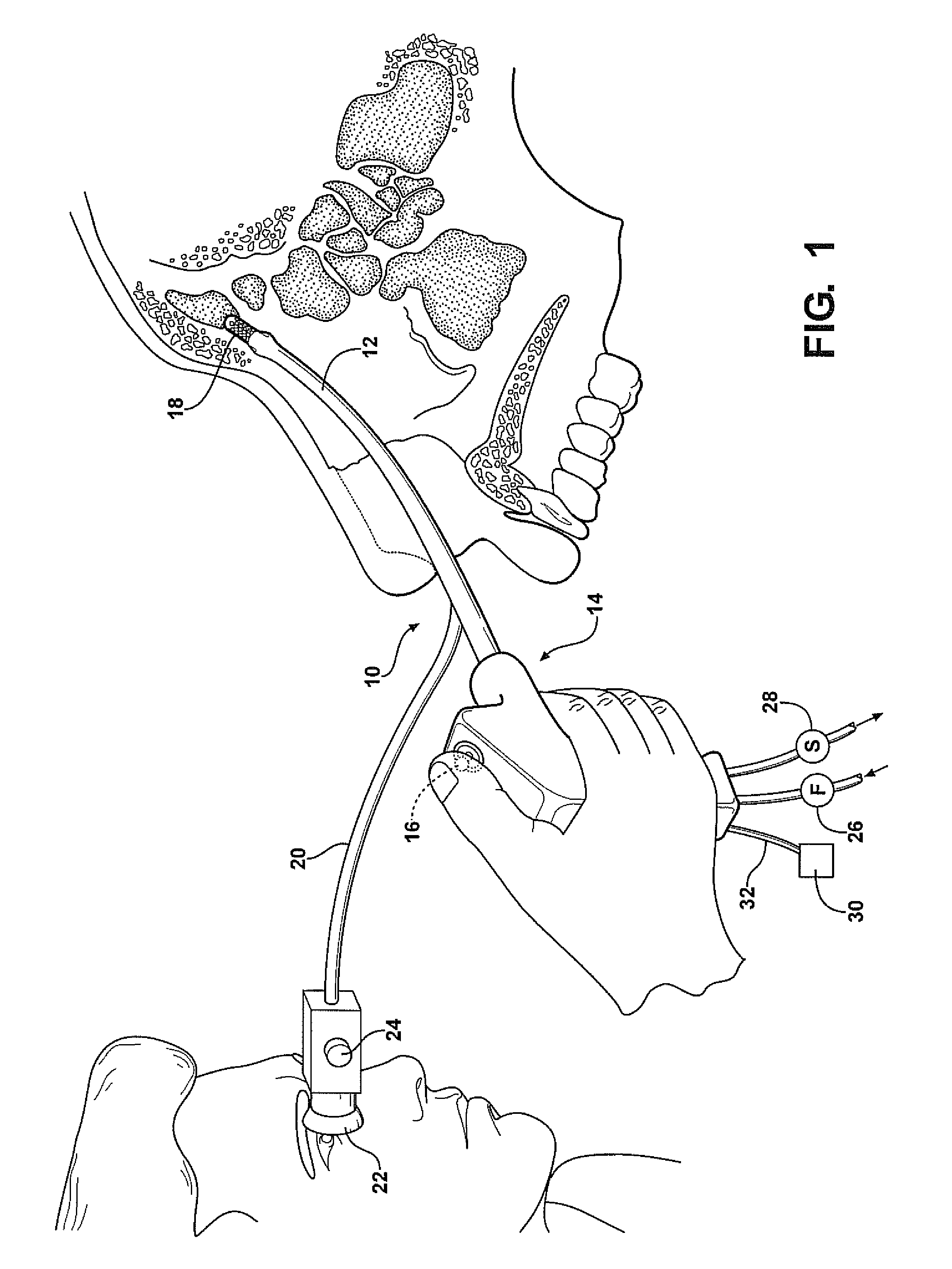
[0016]Referring to the drawings, and FIG. 1 in particular, a surgical endoscope forming a preferred embodiment of the invention, generally indicated at 10, comprises an elongated, tubular section 12 supported by a surgeon at the proximal end with a handle member, generally indicated at 14. The handle 14 is of the pistol grip type having a thumb actuated joystick 16 which the surgeon may use to bend the distal end of the tube 12 to guide it through passages to the operating site, in this case constituting a frontal sinus. The site is then operated on by a rotary tool 18 which is illustrated as a debriding tool in FIG. 1.

[0017]A fiber optic bundle 20 extends through the inside of the tube 12 from a point slightly separated from the proximal end. It ends at an ocular eyepiece 22 which may include appropriate controls such as a dioptric adjustment control 24. It could further include a photo electric converter which converts the optical signals passing through the fiber optic bundle 20 ...


PUM


Abstract

An endoscope for visualizing and operating upon a surgical site within a human body employs an elongated tubular body adapted to be inserted through bodily passages so that the distal end is adjacent the surgical site. The body has a flexible section, at least proximal to the distal end, and manually adjustable bending controls at the proximal end may be manipulated to impose bending forces on the distal end to steer the distal end to the surgical site. A fluid turbine supported for rotation adjacent the distal end is powered by fluids pumped through a passage so as to rotate the turbine. The various cutters and debriding tools may be attached to the distal ends so that they are rotated by the turbine.

Description

CROSS-REFERENCE TO RELATED APPLICATION[0001]This application claims priority of U.S. Provisional Patent Application Ser. No. 61 / 113,929 filed Nov. 12, 2008, which is incorporated herein by reference.FIELD OF THE INVENTION[0002]This invention relates to endoscopes, laparoscopes or the like, and more particularly to a steerable, endoscopically guided fluid turbine powered device with detachable distal tip tools for cutting and burring that can be passed through body cavities to affect cutting and grind / milling of either hard or soft tissue.BACKGROUND OF THE INVENTION[0003]In certain surgical procedures performed within passages of the human body, it may be necessary to remove bone or bard tissue by a grinding or milling process as well as removing softer tissue with a debriding instrument. For example, in sinus surgery it is often necessary to debride soft tissue overlying a bony structure and then grind away portions of the bone to remove infected areas. These surgical operations wer...

Claims


Application Information

Patent Timeline
IPC IPC(8): A61B1/018A61B1/12A61B1/07
CPCA61B1/0051A61B1/015A61B1/018A61B17/24A61B17/32002A61B2019/5217A61B2017/00327A61B2017/00464A61B2017/00553A61B2019/2242A61B2019/2276A61B2017/003A61B2034/742A61B2090/3614A61B34/71
Inventor RONTAL, MICHAEL
Owner RONTAL MICHAEL
Learn More