

Actuator with self-locking assist device
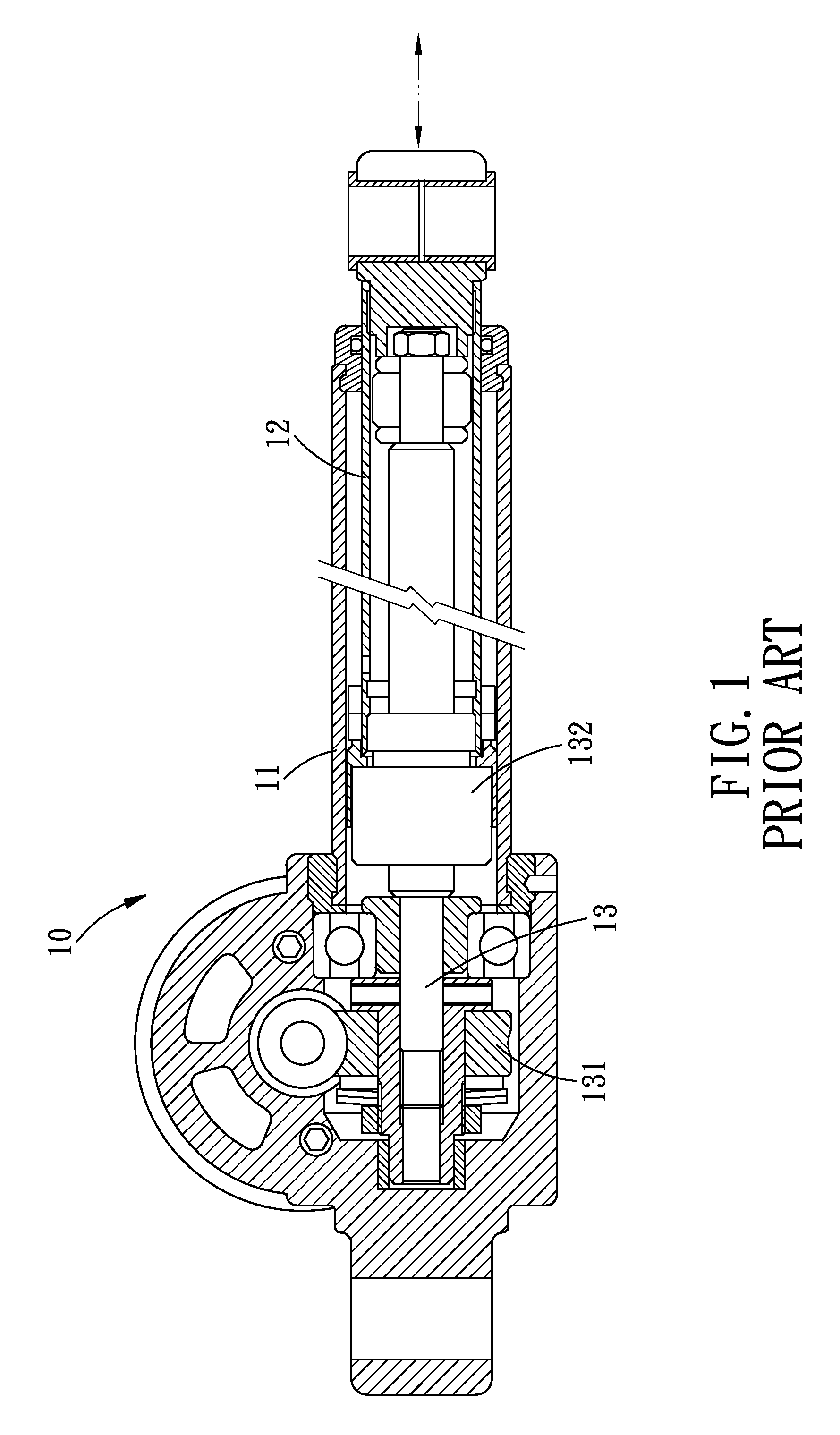
a self-locking, assist device technology, applied in the direction of braking systems, transportation and packaging, gearing, etc., can solve the problems of uncontrollable movement of the actuator b>10/b> and the inability to ensure the safe use of the actuator, so as to improve the self-locking capability of the actuator
- Summary
- Abstract
- Description
- Claims
- Application Information
AI Technical Summary
Benefits of technology
Problems solved by technology
Method used
Image

Examples
Embodiment Construction
[0017]The present invention will be clearer from the following description when viewed together with the accompanying drawings, which show, for purpose of illustrations only, the preferred embodiment in accordance with the present invention.
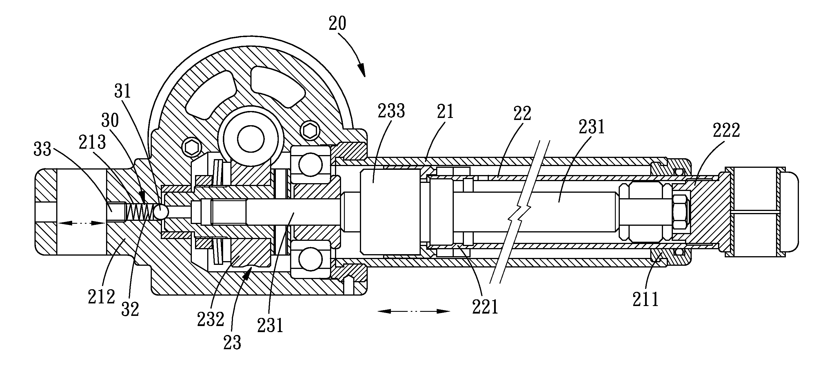
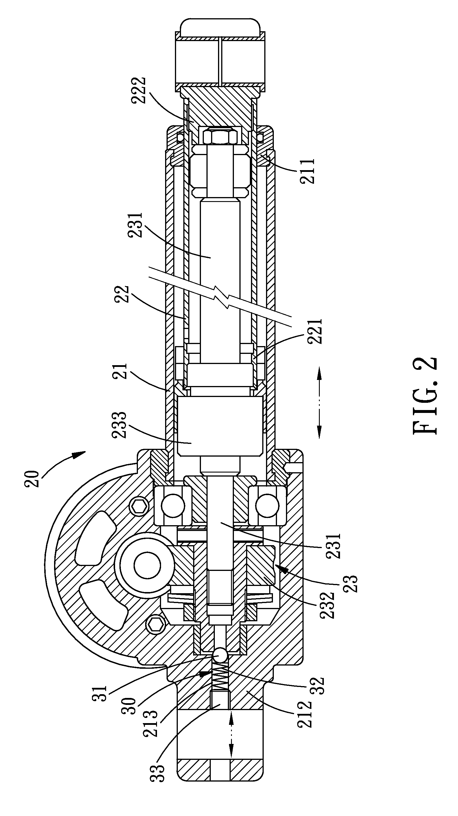
[0018]Referring to FIG. 2, an actuator with self-locking assist device in accordance with a preferred embodiment of the present invention comprises an actuator 20 and a self-locking assist device 30 axially disposed on the actuator 20.
[0019]The actuator 20 comprises a first pipe 21, a second pipe 22 and a transmission assembly 23.
[0020]The first pipe 21 has an open end 211 and a close end 212, and in the close end 212 of the first pipe 21 is axially formed an adjusting hole 213. The second pipe 22 also has an open end 221 and a close end 222, and in the close end 222 of the second pipe 22 is defined an adjusting hole 223. The second pipe 22 has a cross section smaller than that of the first pipe 21. The open ends 221, 211 of the second and first ...
PUM
 Abstract
Description
Claims
Application Information