Device for separating condensate from a coaxial breathing gas line

Active Publication Date: 2010-05-20
DRAGERWERK AG
View PDF6 Cites 28 Cited by
  • Summary
  • Abstract
  • Description
  • Claims
  • Application Information

AI Technical Summary

Benefits of technology

[0005]The basic object of the present invention is to provide a condensate separator for a coaxial tube system, which

Problems solved by technology

Even though it would be possible to provide a separate water trap for each gas duct, this would make handling difficult, because two liquid collecting containers must alway

Method used


Image

  • Device for separating condensate from a coaxial breathing gas line
  • Device for separating condensate from a coaxial breathing gas line
  • Device for separating condensate from a coaxial breathing gas line

Examples


Embodiment Construction

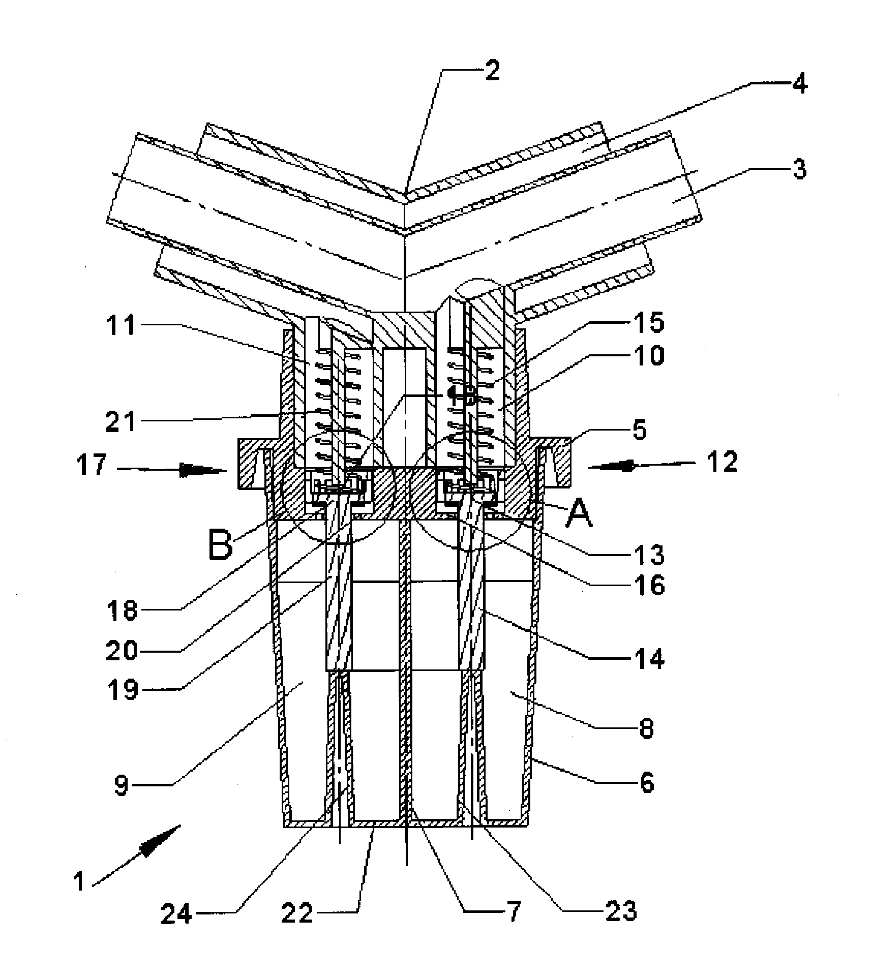
[0018]Referring to the drawings in particular, FIG. 1 schematically illustrates the design of a water trap 1 according to the present invention in the longitudinal section. A breathing gas line 2, shown as a section only, has an inner gas duct 3 and an outer gas duct 4 arranged concentrically thereto with mutually opposite directions of flow for the breathing gas. The breathing gas line 2 is lowered downward at an obtuse angle, and a connecting flange 5 for a liquid collecting container 6 is located at the deepest point.

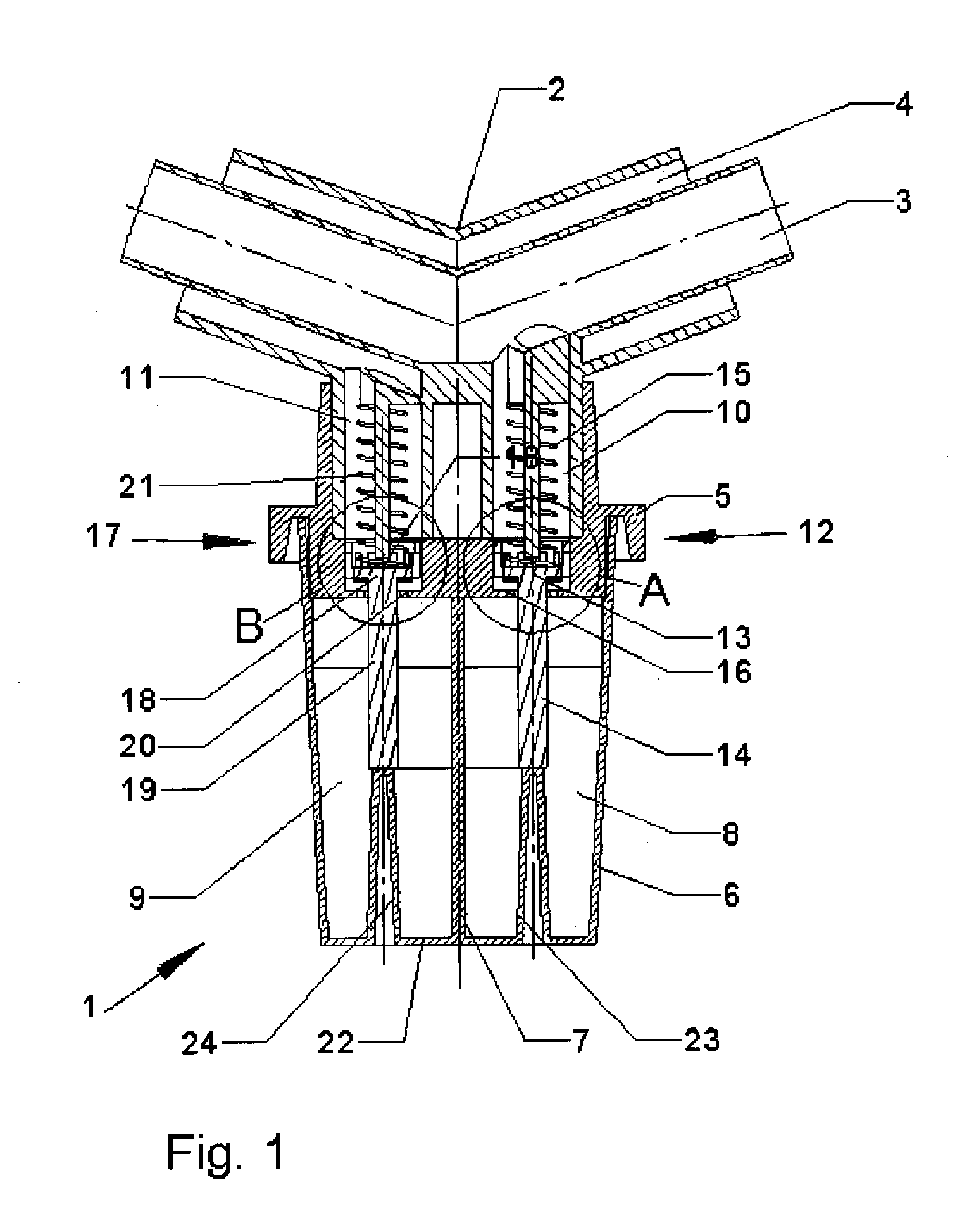
[0019]The liquid collecting container 6 has a partition 7, which separates a first collection volume 8 from a second collection volume 9. A first liquid duct 10 leads from the inner gas duct 3 into the first collection volume 8 and a second liquid duct 11 connects the outer gas duct 4 with the second collection volume 9. A first shut-off valve 12 arranged within the first liquid duct 10 comprises a first valve body 13 with a first pin-like extension 14, which is pres...


PUM


Abstract

A condensate separator is provided for a coaxial tube system, which has an inner gas duct (3) and an outer gas duct (4). A first liquid duct (10) is arranged between the inner gas duct and a first collection volume (8) and a second liquid duct (11) is located between the outer gas duct (4) and a second collection volume (9). The collection volumes (8, 9) are located with a partition (7) in between in a liquid collecting container (6).

Description

CROSS REFERENCE TO RELATED APPLICATIONS[0001]This application claims the benefit of priority under 35 U.S.C. §119 of German Patent Application 10 2008 057 345.0 filed Nov. 14, 2008, the entire contents of which are incorporated herein by reference.FIELD OF THE INVENTION[0002]The present invention pertains to a device for separating condensate from a coaxial breathing gas line.BACKGROUND OF THE INVENTION[0003]A device of this type is known from U.S. Pat. No. 4,457,305. The device, hereinafter called “water trap,” comprises an inlet duct and an outlet duct for breathing gas, which are arranged at an angle to one another. A liquid duct, which can be closed by a valve, is located at the deepest point, in order to remove the condensate from the breathing gas duct. The liquid duct opens into a liquid container, which is pushed over a connecting flange. A pin, which points in the direction of the valve and has such a length that a valve body lifts the valve from its valve seat by the pin w...

Claims


Application Information

Patent Timeline
IPC IPC(8): A61M16/00
CPCA61M16/0808Y10S128/912Y10S128/911
Inventor REINBOTH, THOMASHUSCHKE, ANDRESCHONBECK, AXINJA
Owner DRAGERWERK AG
Why Eureka
Try Eureka