Supercharge Your Innovation With Domain-Expert AI Agents!

Liquid jetting apparatus and liquid supply unit of liquid jetting apparatus

a technology of liquid jetting apparatus and liquid supply unit, which is applied in the direction of printing, etc., can solve the problems of difficult to achieve the desired jetting characteristics, difficult to make the size of the liquid supply unit small, and the size of the valve element and the size of the valve rod are comparatively small, so as to reduce the volume or capacity of the air storage portion, secure the air-tightness of the air discharge passage comparatively easily, and compact

Active Publication Date: 2010-05-20
BROTHER KOGYO KK
View PDF5 Cites 2 Cited by
  • Summary
  • Abstract
  • Description
  • Claims
  • Application Information

AI Technical Summary

Benefits of technology

[0009]In view of the above-described circumstances, an object of the present invention is to provide a liquid jetting apparatus which is provided with an air discharge mechanism, which is capable of discharging air accumulated or stored at an intermediate portion of the liquid supply channel of the liquid supply unit, and in which the size of the apparatus can be made small. Further, another object of the present invention is to provide a liquid jetting apparatus in which there is no need to arrange the liquid supply at a predetermined position at the time of discharging air, and which is capable of easily secure the air-tightness of the air discharge channel. Furthermore, still another object of the present invention is to provide a liquid supply unit which can be used in such liquid jetting apparatus.
[0012]By providing such a structure, it is possible to discharge the air inside the air storage portion by generating the negative pressure, for example with a pump, in the air discharge passage. In other words, it is not necessary to separately provide any valve-element opening mechanism in addition to the pump, and it is also possible to open and close the air discharge passage through (communicating with) the air storage portion by the negative pressure, generated with the pump for discharging the air. Consequently, it is possible to reduce the volume or capacity of the air discharge portion and to make the size of the liquid jetting apparatus such as a printer be small, since the valve-element opening mechanism is unnecessary. Further, when the pump and the air discharge passage of the air discharge mechanism are kept connected all the time by a flexible tube, it is possible to carry out the air discharge operation (air discharge process) without stopping the liquid supply unit at a predetermined position, and it is possible to secure the air-tightness of the air discharge passage comparatively easily.
[0015]By providing such a structure, it is possible to discharge the air inside the air storage portion by generating the negative pressure in the air discharge passage with, for example, a pump provided outside the liquid supply unit, and thus it is not necessary to separately provide any valve-element opening mechanism in addition to the pump. Consequently, it is possible to reduce the volume or capacity of the air storage portion and to make the size of the air supply unit to be small, thereby realizing the small-sized the liquid jetting apparatus such as a printing apparatus, since the valve-element opening mechanism is unnecessary. Further, when the pump and the air discharge passage of the air discharge mechanism are kept connected all the time by a flexible tube, it is possible to carry out the air discharge operation without making the liquid supply unit be stopped at a predetermined position, and it is possible to secure the air-tightness of the air discharge passage comparatively easily.
[0016]According to the present invention, it is possible to provide a liquid jetting apparatus which is capable of discharging air stored in a head unit, and which can be made small or compact. Moreover, it is possible to provide a liquid jetting apparatus in which it is not necessary to arrange the head unit at a predetermined position for discharging air, and it is possible to easily secure the air-tightness of the air discharge passage. Furthermore, it is possible to provide a liquid supply unit which can be used in such a liquid jetting apparatus.

Problems solved by technology

When this air enters into the jetting head, there is a possibility that desired jetting characteristics might not be achieved.
However, when the capacity of the air storage portion is made great or substantial in order to trap more air, it is difficult to make the size of the liquid supply unit be small.
However, in the structure described in Japanese Patent Application Laid-open No. 2007-175996, the size of the valve element and the size of the valve rod are comparatively small.
Therefore, it is difficult to realize the small size of the printing apparatus.

Method used


Image

  • Liquid jetting apparatus and liquid supply unit of liquid jetting apparatus
  • Liquid jetting apparatus and liquid supply unit of liquid jetting apparatus
  • Liquid jetting apparatus and liquid supply unit of liquid jetting apparatus

Examples


Embodiment Construction

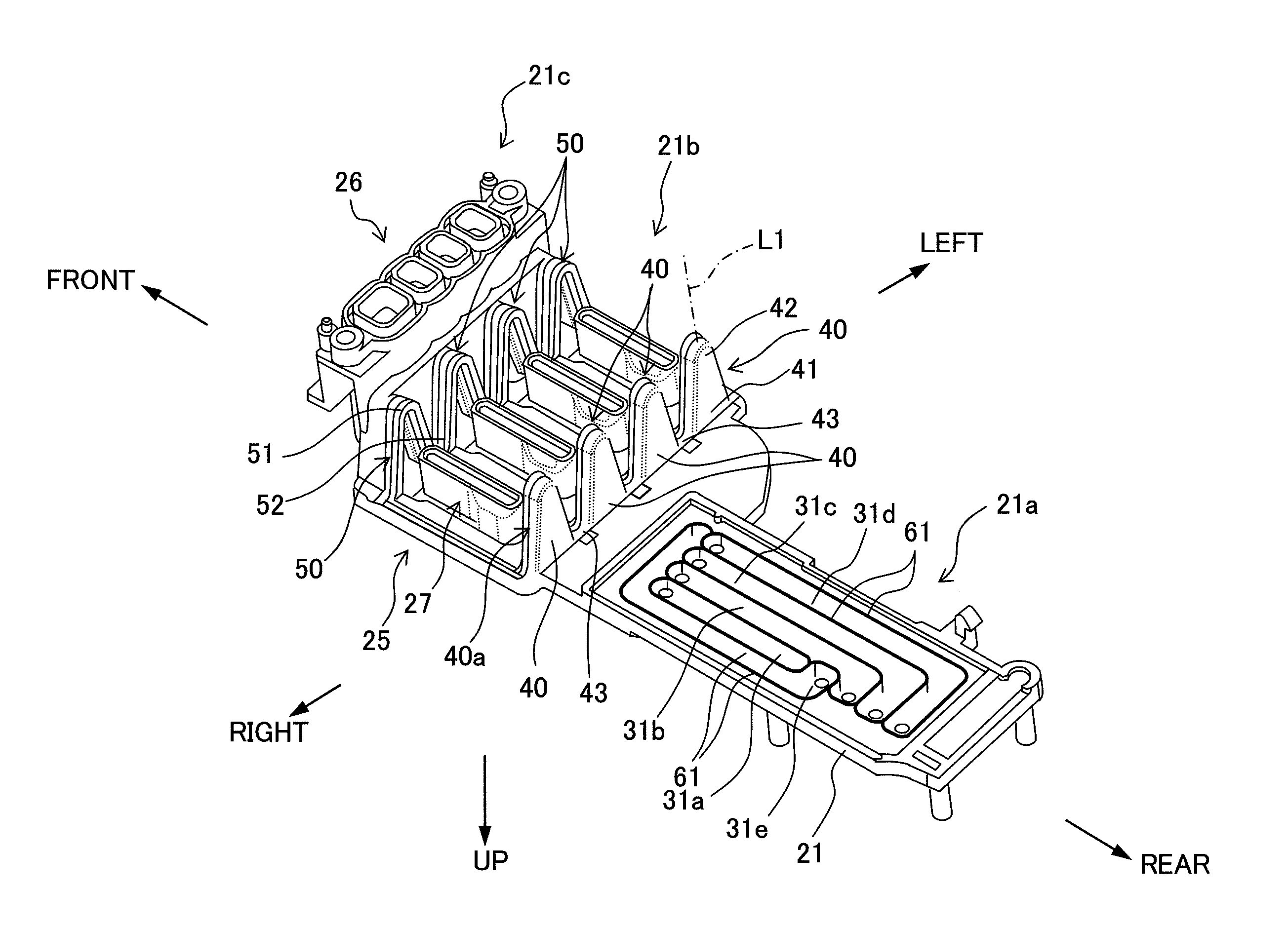
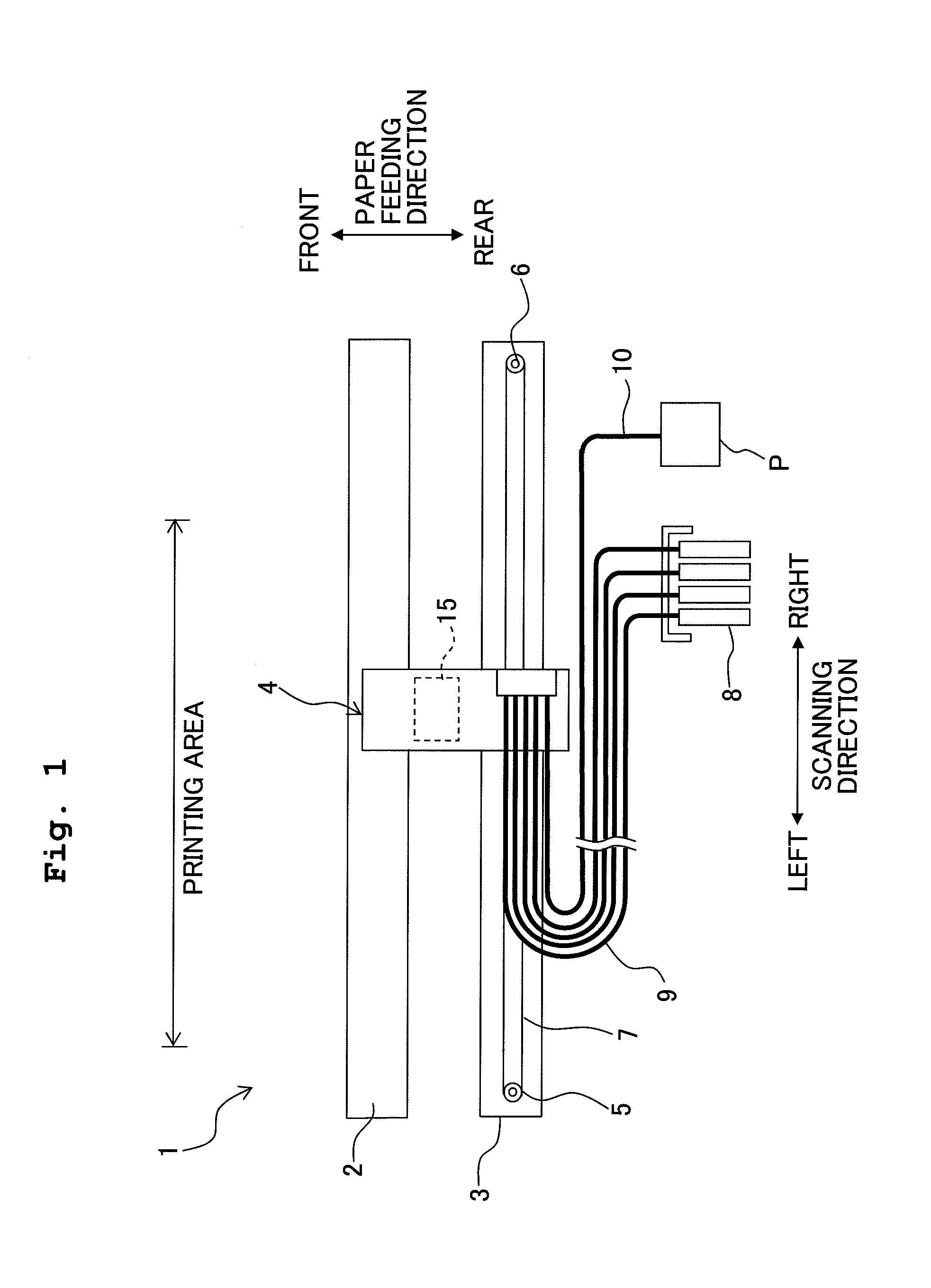
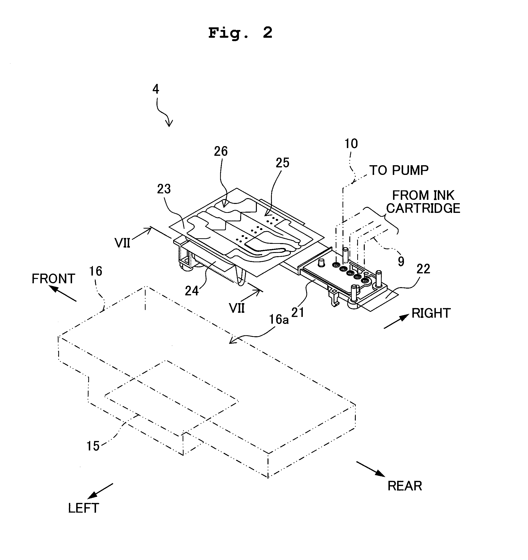
[0033]In the following, a liquid jetting apparatus and a liquid supply unit according to an embodiment of the present invention will be described exemplified by a structure when an ink jet printing apparatus (hereinafter, called as a “printing apparatus”) having a jetting head is used, with reference to the accompanying drawings. In the following description, a direction in which the ink is jetted from the jetting head is a downward direction (down direction, down), and a direction opposite to the direction of jetting is an upward direction (up direction, up). A scanning direction of the jetting head is used synonymously as a left-right direction, and a direction orthogonal to both the up and down direction (vertical direction) and the left-right direction is a frontward direction (front direction, front) and a rearward direction (rear direction, rear). In this patent application, the directions of “left”, “right”, “front”, and a “rear” are defined based on those shown in FIG. 1 as ...


PUM


Abstract

A liquid jetting apparatus includes a liquid jetting head; a liquid supply channel which supplies the liquid to the liquid jetting head; an air discharge mechanism which discharges air existing in the liquid, the air discharge mechanism including an air storage portion, an air discharge passage, a valve, and a flexible member. When a negative pressure is generated in the air discharge passage, the flexible member is deformed to open the valve, and to discharge the air inside the air storage portion via the air discharge passage. Accordingly, the size of the apparatus can be made small while making it possible to discharge the air accumulated in the head unit.

Description

CROSS REFERENCE TO RELATED APPLICATION[0001]The present application claims priority from Japanese Patent Application No. 2008-296008, filed on Nov. 19, 2008, the disclosure of which is incorporated herein by reference in its entirety.BACKGROUND OF THE INVENTION[0002]1. Field of the Invention[0003]The present invention relates to a liquid jetting apparatus such as an ink jet printing apparatus having an air discharge mechanism which discharges air existing in a liquid to be supplied to the jetting head, and to a liquid supply unit of the liquid jetting apparatus.[0004]2. Description of the Related Art[0005]As an ink-jet printing apparatus which is an example of a liquid jetting apparatus, a printing apparatus in which a so-called tube-supply method is adopted has hitherto been known. In this case, an ink is supplied to a jetting head, which reciprocates while facing or be opposite to a recording paper, from an ink cartridge provided in the body of the ink-jet printing apparatus (appa...

Claims


Application Information

Patent Timeline
IPC IPC(8): B41J2/19
CPCB41J2/17509B41J2/19B41J2/17596B41J2/17556
Inventor TAKATA, MASAYUKI
Owner BROTHER KOGYO KK
Features
  • R&D
  • Intellectual Property
  • Life Sciences
  • Materials
  • Tech Scout
  • Unparalleled Data Quality
  • Higher Quality Content
  • 60% Fewer Hallucinations
Learn More