
Scanning endoscope, scanning endoscope processor, and scanning endoscope apparatus

a scanning endoscope and processor technology, applied in the field of scanning endoscopes, can solve the problems of difficult to observe certain types of subjects using such a scanning endoscope, and difficulty in recognizing the status of the inner surfa

Active Publication Date: 2010-05-20
HOYA CORP
View PDF14 Cites 10 Cited by
  • Summary
  • Abstract
  • Description
  • Claims
  • Application Information

AI Technical Summary

Benefits of technology

[0006]Therefore, an object of the present invention is to provide a scanning endoscope that can photograph and / or film an optical image of the subject around an insertion tube with a direct front view.

Problems solved by technology

However, it is difficult to observe certain types of subjects using such a scanning endoscope.
This is because it is difficult to adjust the position of the insertion tube in a thin lumen, such as a bronchial periphery, so that the distal end of the insertion tube faces the inner surface of the thin lumen.
However, it is difficult to recognize the status of the inner surface by the image of the inner surface photographed and / or filmed from such a large angle of incidence.

Method used


Image

  • Scanning endoscope, scanning endoscope processor, and scanning endoscope apparatus
  • Scanning endoscope, scanning endoscope processor, and scanning endoscope apparatus
  • Scanning endoscope, scanning endoscope processor, and scanning endoscope apparatus

Examples


Embodiment Construction

[0030]The present invention is described below with reference to the embodiment shown in the drawings.

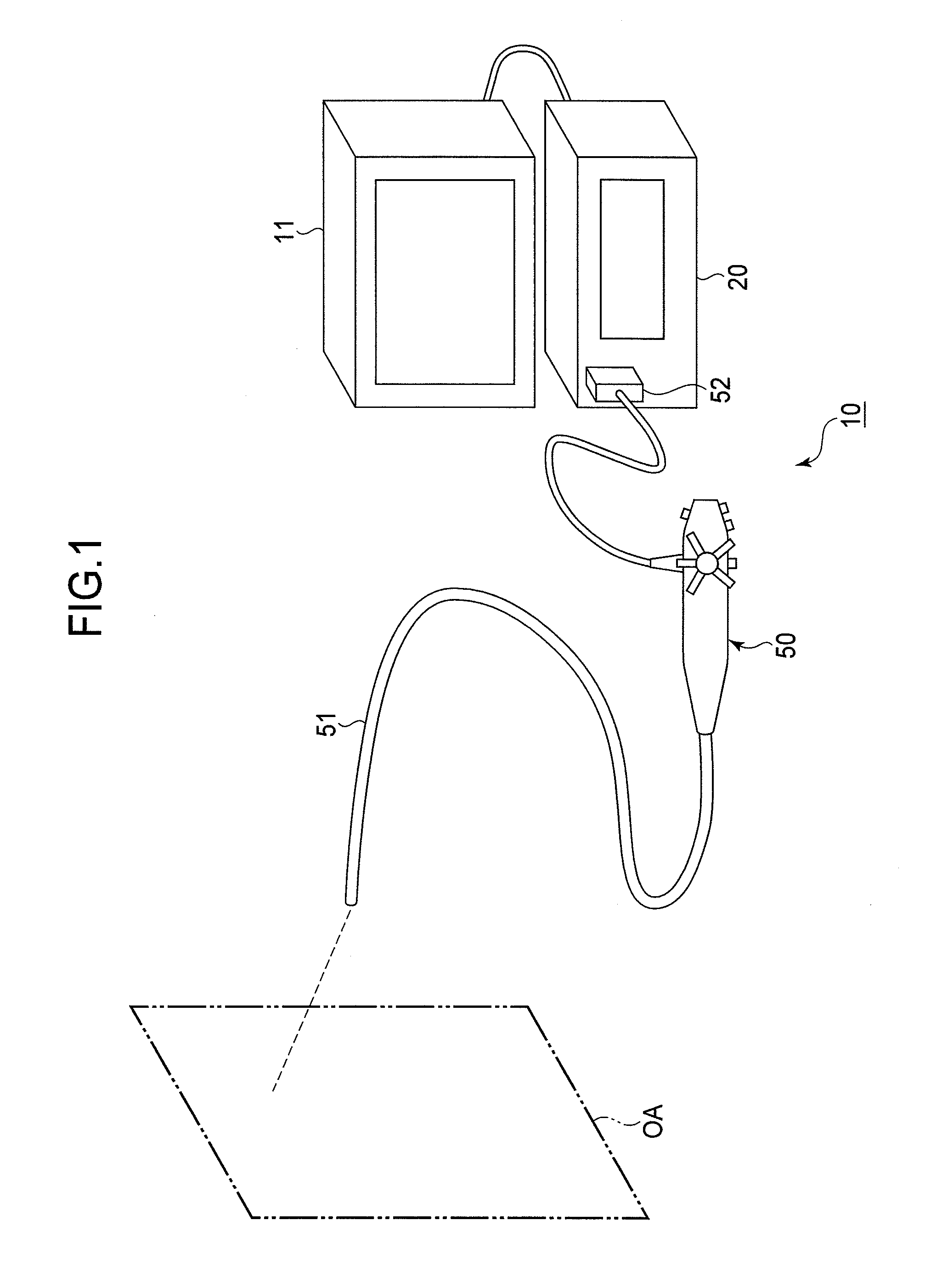
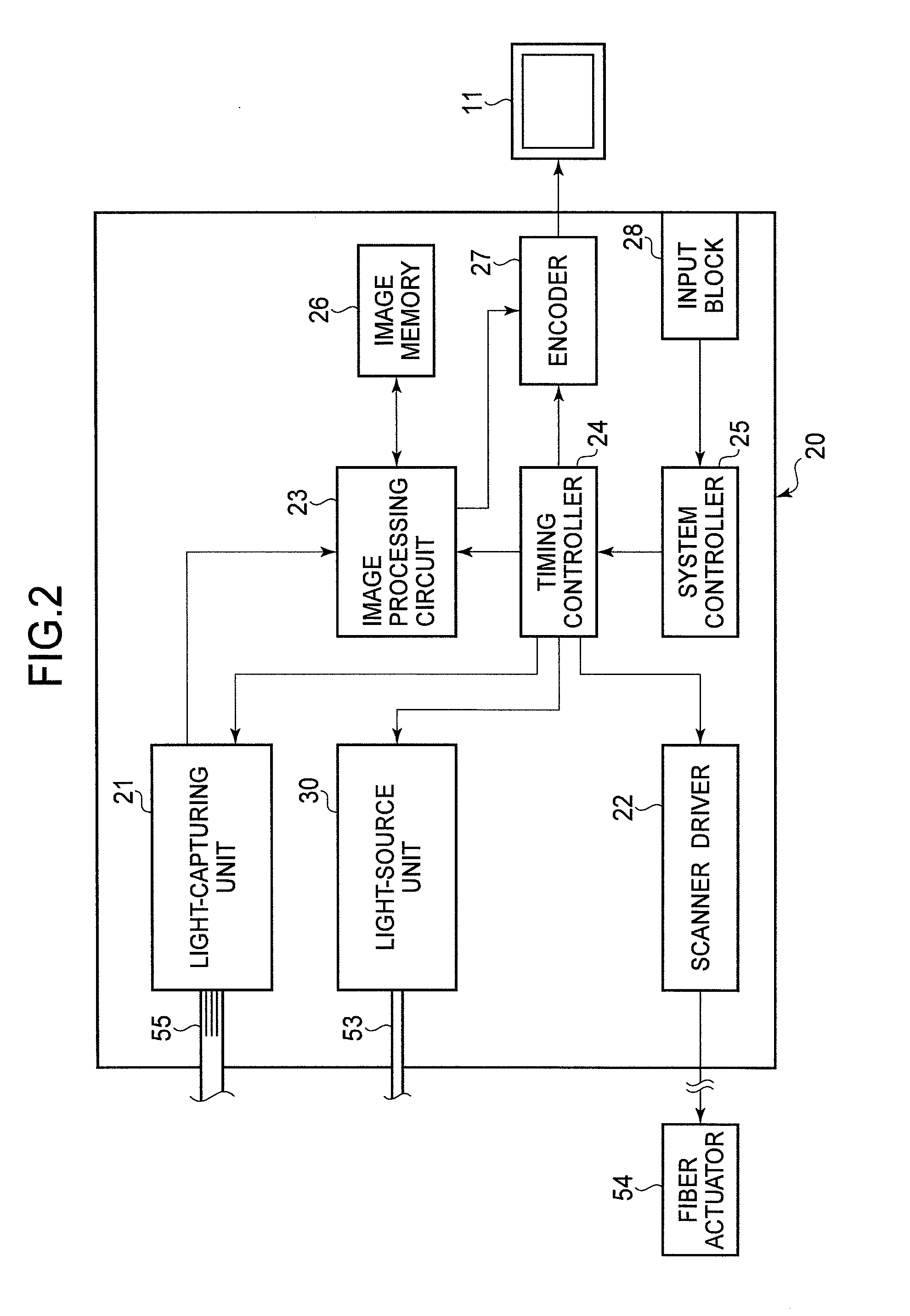
[0031]In FIG. 1, the scanning endoscope apparatus 10 comprises a scanning endoscope processor 20, a scanning endoscope 50, and a monitor 11. The scanning endoscope processor 20 is connected to the scanning endoscope 50 and the monitor 11.

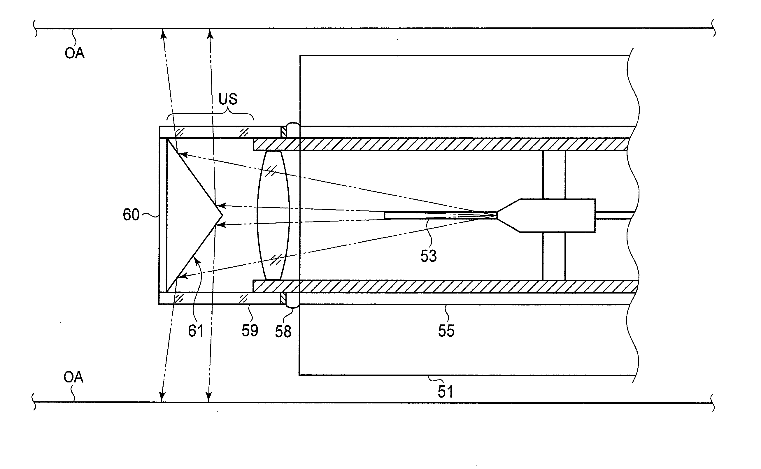
[0032]Hereinafter, an emission end of an illumination fiber (not depicted in FIG. 1) and incident ends of image fibers (not depicted in FIG. 1) are ends mounted in the distal end of the insertion tube 51 of the scanning endoscope 50. In addition, an incident end of the illumination fiber and emission ends of the image fibers are ends mounted in a connector 52 that connects to the scanning endoscope processor 20.

[0033]The scanning endoscope processor 20 provides light that is shined on an observation area (see “OA” in FIG. 1). The light emitted from the scanning endoscope processor 20 is transmitted to the distal end of the insertion tube 51 through ...


PUM


Abstract

A scanning endoscope, comprising a first transmitter, an actuator, and a mirror, is provided. The first transmitter emits a beam of radiant light from an emission end. The actuator moves the emission end in a direction perpendicular to an emission direction. The mirror is arranged from the emission end in the emission direction when the emission end is on a predetermined standard point. The mirror comprises a reflection surface around a first straight line. The distance between a first position on the first straight line to any second position on the reflection surface increases as the first position is moved in the first direction. The reflection surface reflects the radiant light emitted from the first transmitter toward the observation area around the first straight line.

Description

BACKGROUND OF THE INVENTION[0001]1. Field of the Invention[0002]The present invention relates to a scanning endoscope that photographs and / or films an optical image of a subject that is around an insertion tube of the scanning endoscope.[0003]2. Description of the Related Art[0004]Japanese Patent No. 3943927 discloses a scanning endoscope which photographs and / or films an optical image of an observation area by scanning the observation area with light shined on a minute point in the area and successively capturing reflected light at the illuminated points. In a general scanning endoscope, light for illumination is transmitted through an optical fiber from a stationary incident end to a movable emission end and a scanning operation is carried out by successively moving the emission end of the optical fiber.[0005]A general scanning endoscope is designed so that a field of vision of the scanning endoscope is in front of a distal end of an insertion tube of the scanning endoscope. Howev...

Claims


Application Information

Patent Timeline
IPC IPC(8): A61B1/045A61B1/06
CPCA61B1/0008A61B1/00098A61B1/00172A61B1/042A61B1/0615G02B26/103G02B23/2423G02B23/2469H04N2005/2255A61B1/00167A61B1/07H04N23/555
Inventor SUGIMOTO, HIDEO
Owner HOYA CORP
Features
  • Generate Ideas
  • Intellectual Property
  • Life Sciences
  • Materials
  • Tech Scout
  • Unparalleled Data Quality
  • Higher Quality Content
  • 60% Fewer Hallucinations
Learn More