Transmission mechanism with intermittent output movement

Active Publication Date: 2010-05-27
NAT SUN YAT SEN UNIV
View PDF3 Cites 9 Cited by
  • Summary
  • Abstract
  • Description
  • Claims
  • Application Information

AI Technical Summary

Benefits of technology

[0005]The primary objective of the present invention is to provide a transmission mechanism with intermittent output movement capable of lowering the load

Problems solved by technology

However, the cost for forming the annular groove is high, and the heat treatment after formation of the annular groove is difficult.
Furthermore, the roller rotatably mounted to a side of the roller arm acts like a cantilever beam, which is liable to wobble and deform during high speed operation, leading to abnormal wear to the annular groove and the roller.
Further, the plan

Method used


Image

  • Transmission mechanism with intermittent output movement
  • Transmission mechanism with intermittent output movement
  • Transmission mechanism with intermittent output movement

Examples


Embodiment Construction

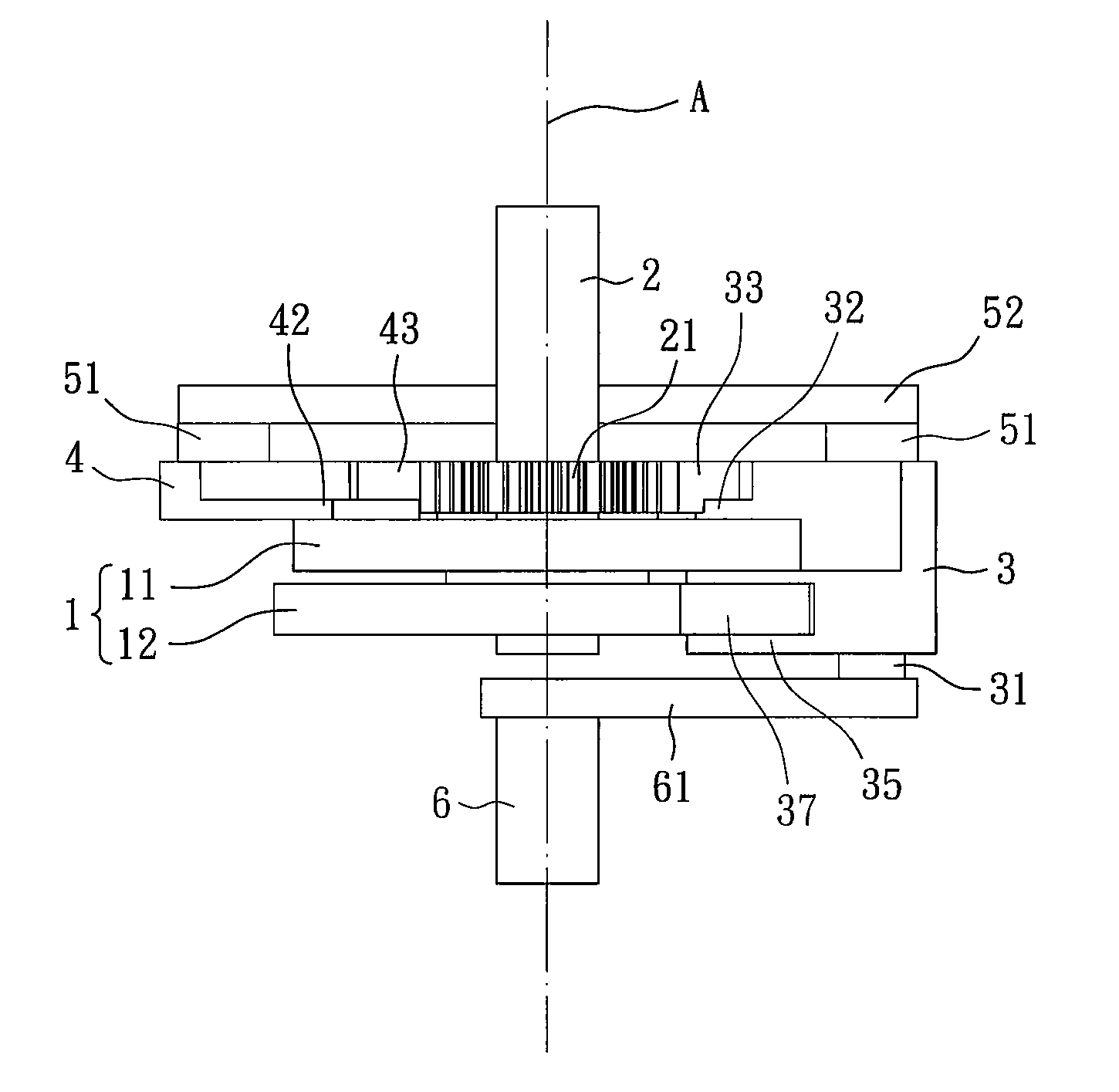
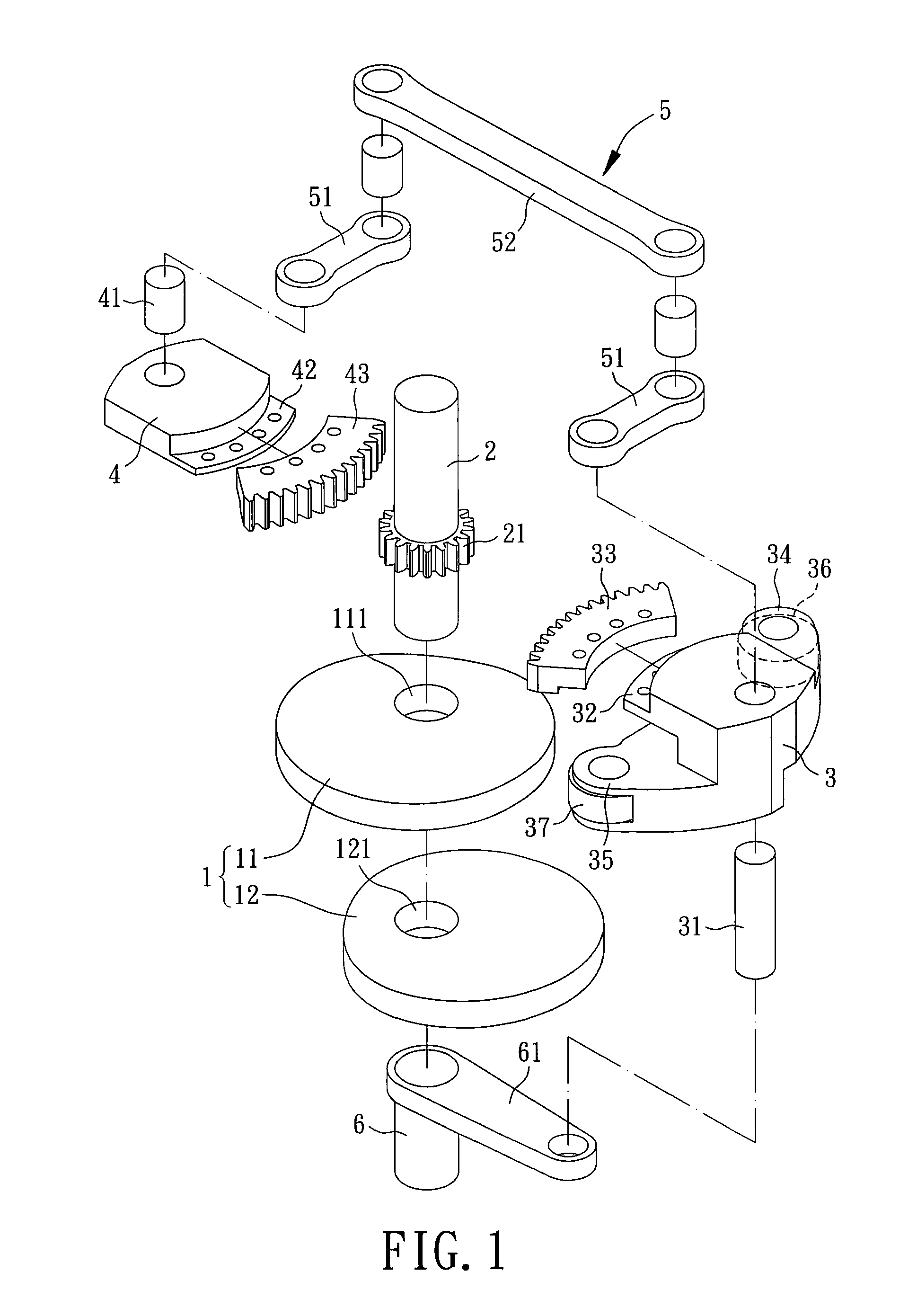
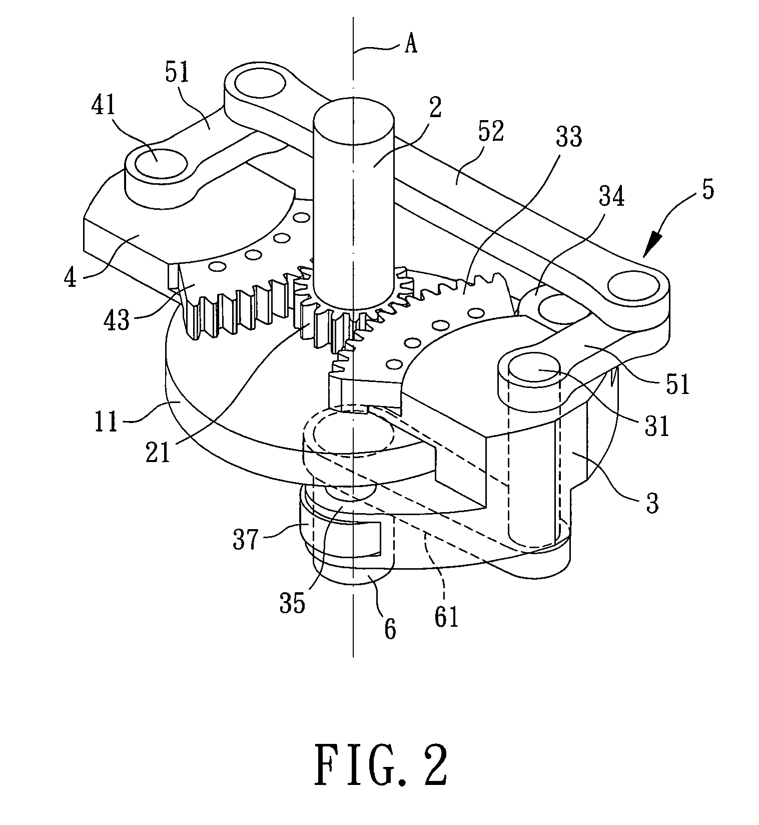
[0029]FIG. 1 shows a transmission mechanism with intermittent output movement of a first embodiment according to the preferred teachings of the present invention. The transmission mechanism includes a conjugate cam unit 1, an output shaft 2, a first rocker 3, a second rocker 4, a transmission unit 5, and an input shaft 6.

[0030]The conjugate cam unit 1 includes first and second cams 11 and 12 that are preferably plate cams and have different shapes. The first cam 11 has an axial hole 111 preferably located in a center of a base circle of the first cam 11. The second cam 12 has an axial hole 121 preferably located in a center of a base circle of the second cam 12. The first and second cams 11 and 12 are superimposed with the axial holes 111 and 121 aligned with each other. The superimposed first and second cams 11 and 12 can be fixed to a frame by a pin or the like.

[0031]The output shaft 2 is rotatably extended through the axial holes 111 and 121 of the first and second cams 11 and 12...


PUM


Abstract

A transmission mechanism with intermittent output movement includes an output shaft rotatably mounted to first and second cams and a sun gear mounted to the output shaft. A first rocker includes a first planet gear meshed with the sun gear and first and second rollers rotatably mounted on opposite sides of the first planet gear and respectively in contact with the first and second cams. A second rocker includes a second planet gear meshed with the sun gear. An end of a first connecting rod is mounted to the first rocker. An end of a second connecting rod is mounted to the second rocker. Two ends of a link are rotatably mounted to the other ends of the first and second connecting rods. A planet gear carrier is mounted to an input shaft coaxial to the input shaft and includes an end rotatably mounted to the first rocker.

Description

BACKGROUND OF THE INVENTION[0001]1. Field of the Invention[0002]The present invention relates to a transmission mechanism with intermittent output movement and, more particularly, to a transmission mechanism capable of converting continuous input movement into intermittent output movement.[0003]2. Description of the Related Art[0004]Taiwan Patent Publication No. 1272351 discloses an adjustable reciprocating movement mechanism including a power device using a motor as a power source, a power input mechanism, a variable speed mechanism, and a power output mechanism. The power input mechanism includes a driving gear driven by the motor and a driven gear driven by the driving gear. The variable speed mechanism includes a base having an annular groove in which a roller is slideably received. An input shaft extends through the base and includes a first end to which the driven gear is mounted and a second end to which a planet gear carrier is mounted. A planet gear and a roller arm are rot...

Claims


Application Information

Patent Timeline
IPC IPC(8): F16H19/00
CPCF16H35/02Y10T74/19186F16H37/12
Inventor TSAY, DER-MINCHEN, HSIN-PAOHSU, HSIEN-WENHUANG, CHIH-WEI
Owner NAT SUN YAT SEN UNIV
Why Eureka
Try Eureka