Bumper reinforcement member

Active Publication Date: 2010-05-27
ASTEER
View PDF2 Cites 17 Cited by
  • Summary
  • Abstract
  • Description
  • Claims
  • Application Information

AI Technical Summary

Benefits of technology

[0015]Above-said “a bumper reinforcement member of a hollow section” refers to a bumper reinforcement member of a structure interiorly including a hollow portion continuing in an extending direction (normally, left and right direction of the vehicle) of the bumper reinforcement member. Whether the rear face is closed or opened is not particularly limited. The bumper reinforcement member of the present invention can be manufactured through aluminum extrusion, grind molding, and sheet-meal processing. The sheet-meal processing is preferable as the bumper reinforcement member can be easily and inexpensively manufactured.
[0031]The bumper reinforcement member of the present invention has a structure particularly suited to the bumper reinforcement member made of sheet-meal, which is easy and inexpensive to manufacture. Specifically, enlargement can be prevented as the supplementary reinforcement member is housed in the outer shape of the main reinforcement member. The increase in manufacturing cost is prevented since the processing in the formation of the large groove and the small groove is easy. Since the supplementary reinforcement member is housed in the outer shape of the main reinforcement member and the processing of the large groove and the small groove is easy, a huge variety of designs are adaptable. The mutual suppression of deformations of the large groove and the small groove, which is a technical feature of the present invention, is exhibited even in the bumper reinforcement member made of sheet-meal, and thereby the peak load and the gross amount of energy absorption can be increased.

Problems solved by technology

The bumper reinforcement member disclosed in JP2005-170234A has a problem in that the deformation of each vertical wall is not uniform as the vertical wall is long.
Furthermore, the peak of the load to be absorbed greatly increases or decreases (see graph of FIG. 5) and a stable energy absorption property may not be obtained as a whole.
Moreover, since the load to be absorbed increases and decreases, the energy absorption inevitably becomes small as a whole.
However, since the supplementary reinforcement member is attached to the front face of the main reinforcement member, and the supplementary reinforcement member greatly projects out from the front face of the main reinforcement member, the bumper reinforcement member inevitably becomes large.
Increase in weight also becomes a problem.
Variety of design is also limited.
Thus, the bumper reinforcement member disclosed in JP2003-237507A is difficult to use in light automobiles to which weight limits and layout limits are strictly imposed and automobiles having high designability.
However, the bumper reinforcement member is enlarged and the weight becomes excessively large if each face is thickened.
The manufacturing cost becomes high if the high strength material is used.
Making the cross section complicating deprives the variety of design of the bumper reinforcement member and has a possibility of influencing the design of the entire vehicle.
Therefore, miniaturization, reduction in manufacturing cost, and simplification of the cross section become important issues in enhancing the energy absorption property.

Method used


Image

  • Bumper reinforcement member
  • Bumper reinforcement member
  • Bumper reinforcement member

Examples


Embodiment Construction

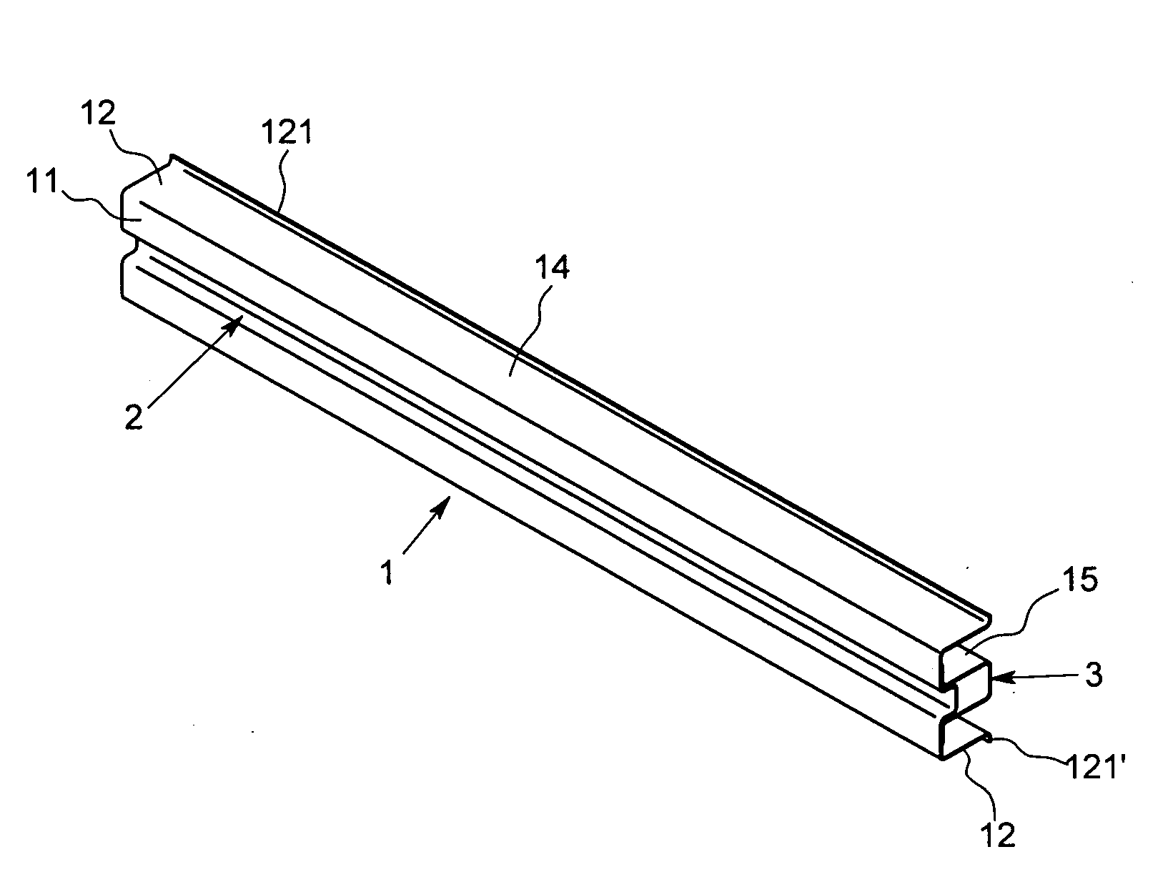
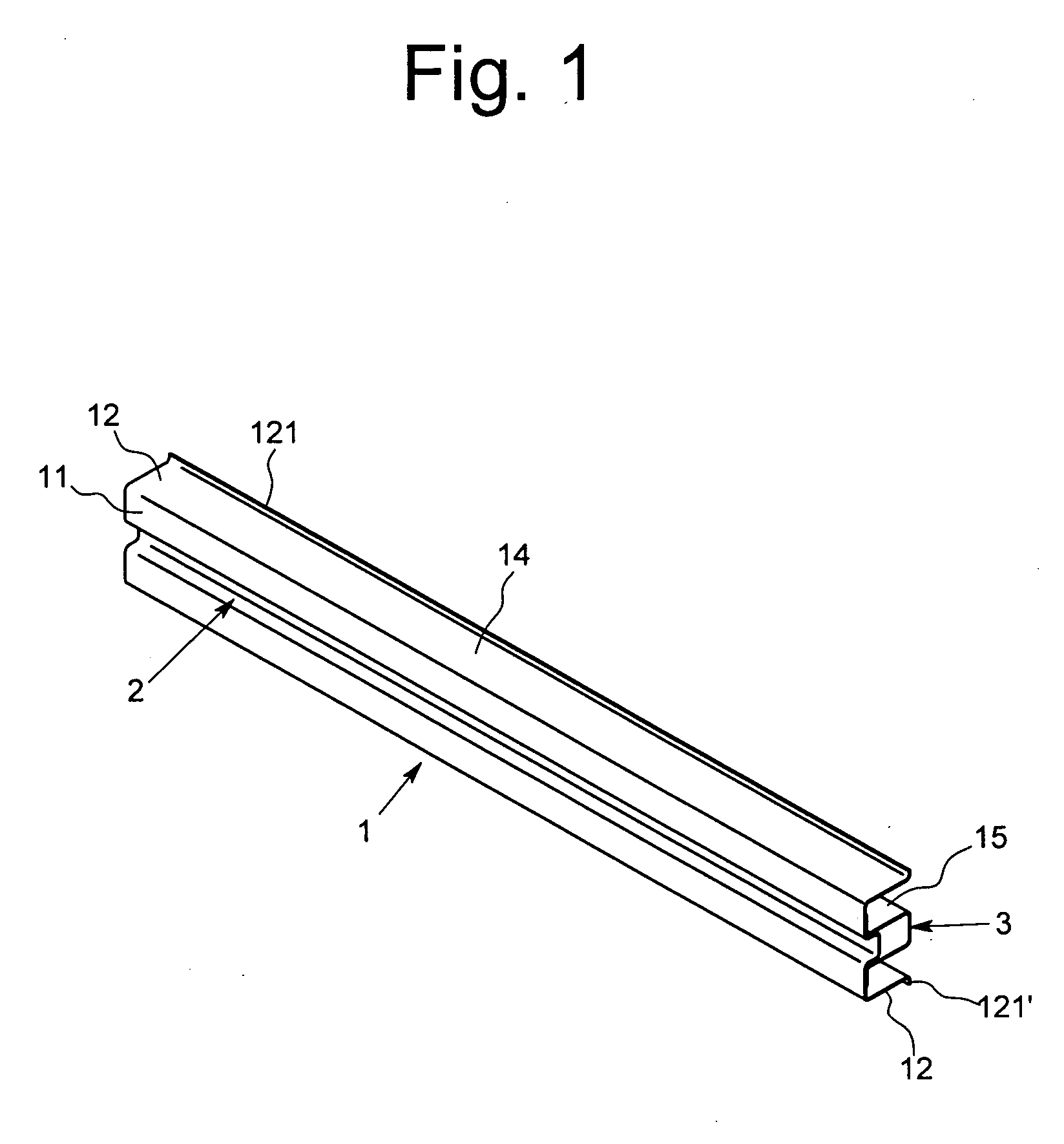
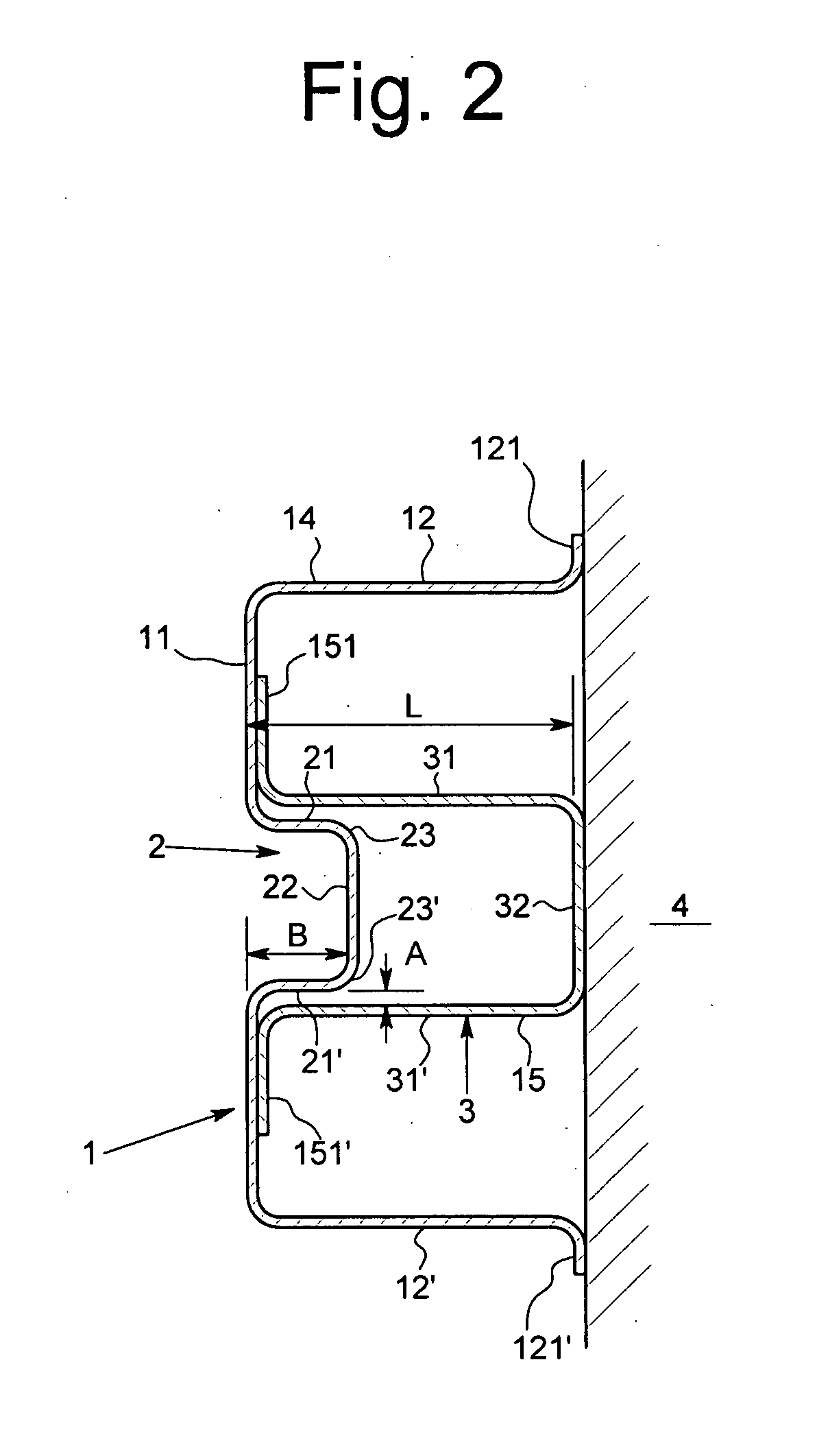
[0053]The best modes for carrying out the present invention will be described below with reference to the drawings. FIG. 1 is a perspective view illustrating a bumper reinforcement member 1 of one example in which a small groove 2 is formed at a main reinforcement member 14 of a rear face opened sectional structure and a supplementary reinforcement member 15 is a large groove 3, and FIG. 2 is a sectional view illustrating the bumper reinforcement member 1 of the present example. In FIG. 2 and subsequent sectional views, rear edges 121, 121′ of the lateral faces (upper lateral face 12, lower lateral face 12′) and groove bottom face 32 of the large groove 3 are connected to a specific vehicle frame assembled with a mold steel and a pipe, and a specific impact absorption member projected out from the vehicle frame, where a face to connect the rear edge (upper rear edge 121, lower rear edge 121′) of the upper and lower lateral faces 12, 12′ and the groove bottom face 32 of the large gro...


PUM


Abstract

A bumper reinforcement member 1 includes a small groove 2 and a large groove 3. The large groove 3 is arranged to encompass the small groove 2 inside the groove. When the bumper reinforcement member 1 is deformed, directions of the deformation of the lateral face of the small groove and the deformation of the lateral face of the large groove are oppose to each other, and thus the peak load and the energy absorption amount of the bumper reinforcement member 1 can be increased with a simple configuration.

Description

BACKGROUND OF THE INVENTION[0001]1. Field of the Invention[0002]The present invention relates to a bumper reinforcement member configuring a bumper of a vehicle.[0003]2. Description of the Related Art[0004]The bumper of a vehicle is configured by a bumper reinforcement member for absorbing impact, and a bumper cover for covering the bumper reinforcement member. The bumper reinforcement member absorbs impact by deforming a hollow section (plastic deform of a face that forms the section). In general, a superior bumper has a high maximum value (peak load) in a three-point bending test applying a load at one point and supports a test piece at other two points, a larger deformed amount and the larger value of integral (in other words, impulse or gross amount of energy absorption). The energy absorption property in the bumper reinforcement member can be enhanced by thickening each face that is plastic-deformed, using a high strength material, or making the cross section complicating.[0005...

Claims


Application Information

Patent Timeline
IPC IPC(8): B60R19/18
CPCB60R2019/1826B60R19/18
Inventor WAKABAYASHI, MASAFUMISHIMOTSU, KOUJI
Owner ASTEER
Why Eureka
Try Eureka