Solar canopy support system

a solar panel and support system technology, applied in the direction of heat collector mounting/support, manufacturing tools, light and heating equipment, etc., can solve the problems of inefficient and overly expensive prior known systems for elevating structures to support solar collector panels, and the installation of known systems takes an excessive amount of tim

Inactive Publication Date: 2010-06-03
ENGIE SERVICES U S INC
View PDF74 Cites 68 Cited by
  • Summary
  • Abstract
  • Description
  • Claims
  • Application Information

AI Technical Summary

Benefits of technology

[0011]These and other features and advantages of the present invention will be made more apparent through a consideration of the following detailed

Problems solved by technology

Beyond the photo-electro voltaic cell technology itself are the problems of placement and support of the solar collector panels.
Prior known systems for elevated structures for supporting the solar collector panels are inefficient a

Method used


Image

  • Solar canopy support system
  • Solar canopy support system
  • Solar canopy support system

Examples


Embodiment Construction

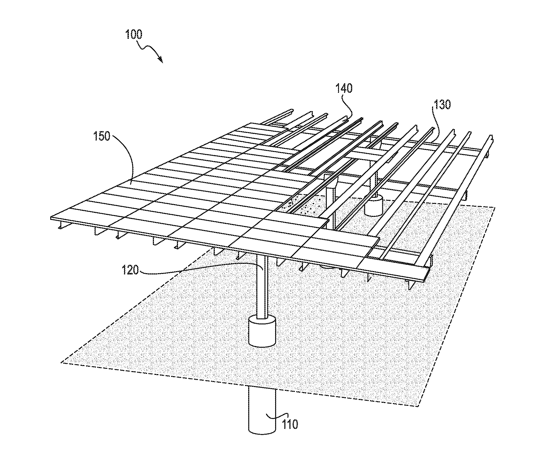
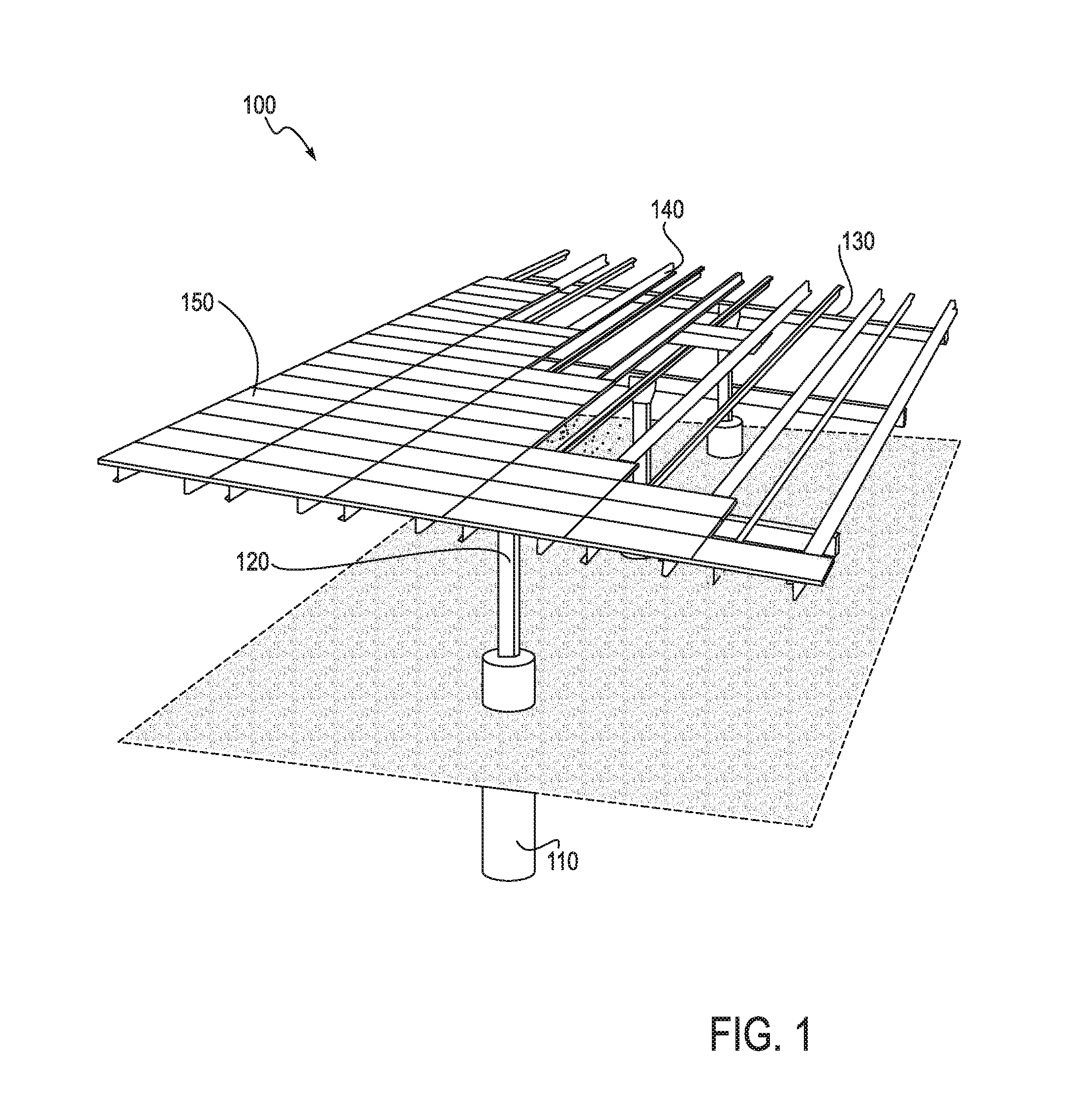
[0027]FIG. 1 is a top perspective view of one embodiment of the present invention. Solar canopy support system 100 is shown—both above and below grade level (shown as gray-filled plane). Reinforced concrete bollard 110 rests in the ground and provides the support for beam support column 120. Beam support column 120 is attached to reinforced concrete bollard 110 by any known method, by embedding a lower portion of beam support column 120 in the concrete of beam support column 120 while still wet or placing it in a suitable hole and then pouring the concrete around it, or by embedding bolts in the reinforced concrete bollard 110 with protruding ends which permit attachment of the beam support column 120 by bolting, which will be described in more detail with reference to FIGS. 5-7.

[0028]The beam support columns 120 supports zee channel support beams 130. The zee channel support beam 130 supports at least two zee channels 140. This provides the solar canopy support system for supportin...


PUM

PropertyMeasurementUnit
Angleaaaaaaaaaa
Angleaaaaaaaaaa
Pressureaaaaaaaaaa

Abstract

The solar canopy support system has at least two beam support columns. Each beam support column has a first end connected to a ground surface and extends substantially vertically along a longitudinal axis from the first end to a second end. There is also a zee channel support beam connected at the second end of each beam support column. The zee channel support beam includes a longitudinal axis within about 0 degrees to about 30 degrees of perpendicular to the longitudinal axis of each beam support column. There are also two or more zee channels. Each zee channel has a first end connected to an upper portion of one zee channel support beam and has a second end connected to an upper portion of another zee channel support beam. Each zee channel includes a longitudinal axis substantially perpendicular to the longitudinal axis of each zee channel support beam; at least one solar power array connected on an upper portion of at least two zee channels.

Description

I. COPYRIGHT NOTICE AND AUTHORIZATION[0001]This patent document contains material which is subject to copyright protection.[0002]© Copyright 2009. Chevron Energy Solutions. All rights reserved.[0003]With respect to this material which is subject to copyright protection. The owner, Chevron Energy Solutions has no objection to the facsimile reproduction by any one of the patent disclosure, as it appears in the Patent and Trademark Office patent files or records of any country, but otherwise reserves all rights whatsoever.II. FIELD OF THE INVENTION[0004]This invention relates to system and method for support of a solar canopy.III. BACKGROUND OF THE INVENTION[0005]Solar energy is a clean, renewal energy source. Photo-electro voltaic cell technology is increasing rapidly and makes installation of solar collector panels housing the photo-electro voltaic cells more and more economically feasible. Beyond the photo-electro voltaic cell technology itself are the problems of placement and supp...

Claims


Application Information

Patent Timeline
IPC IPC(8): H01L31/042A47F7/00B23P11/00
CPCE04H6/025F24J2/045F24J2/5232F24J2/525F24J2/5256Y10T29/49355Y02B10/20Y02E10/44Y02E10/47Y10T29/49826F24J2002/4661F24S20/67F24S25/12F24S25/617F24S2025/6002F24S25/634
Inventor POTTER, DAVID S.MUNOZ, JEFF P.
Owner ENGIE SERVICES U S INC
Why Eureka
Try Eureka