Display unit with roller assembly shelving

a technology of display units and shelves, applied in the direction of rollers, show hangers, serving tables, etc., can solve the problems of limited display unit applications, heavy or large shelving, and generally complex and/or costly manufacturing

Inactive Publication Date: 2010-06-03
HAMLON
View PDF29 Cites 123 Cited by
  • Summary
  • Abstract
  • Description
  • Claims
  • Application Information

AI Technical Summary

Benefits of technology

[0018]In a second aspect the present invention consists in a product display unit, said unit comprising at least one shelf, said at least one shelf comprising a retaining member for holding at least two roller track assemblies in alignment to form a planar product support surface, said retaining member comprising a first retaining channel for engaging a portion of at least two roller track assemblies, said retaining member comprising a second retaining channel for engaging at least one product stop member, wherein said second retaining channel is positioned with respect to said first retaining channel so as to direct a product stop member engaged with said second retaining channel to project above the plane of the product support surface formed by roller track assemblies engaged with said first retaining channel so as to be able to engage a product resting on a planar product support surface formed by at least two roller track assemblies aligned by engagement with said first retai

Problems solved by technology

Disadvantage of prior art roller assemblies is that they are generally suited to single or limited display unit applications, are generally complex and/or costly to manufacture, and/or are designed to be mounted on existing shelving rather than to replace prior art shelving.
Prior art display units using roller shelving are heavier or larger than desired, interfere with view of the products displayed, and are inefficient in use of materials, inter alia.
In many instances the “riser” is removably clipped to the assem

Method used


Image

  • Display unit with roller assembly shelving
  • Display unit with roller assembly shelving
  • Display unit with roller assembly shelving

Examples


Embodiment Construction

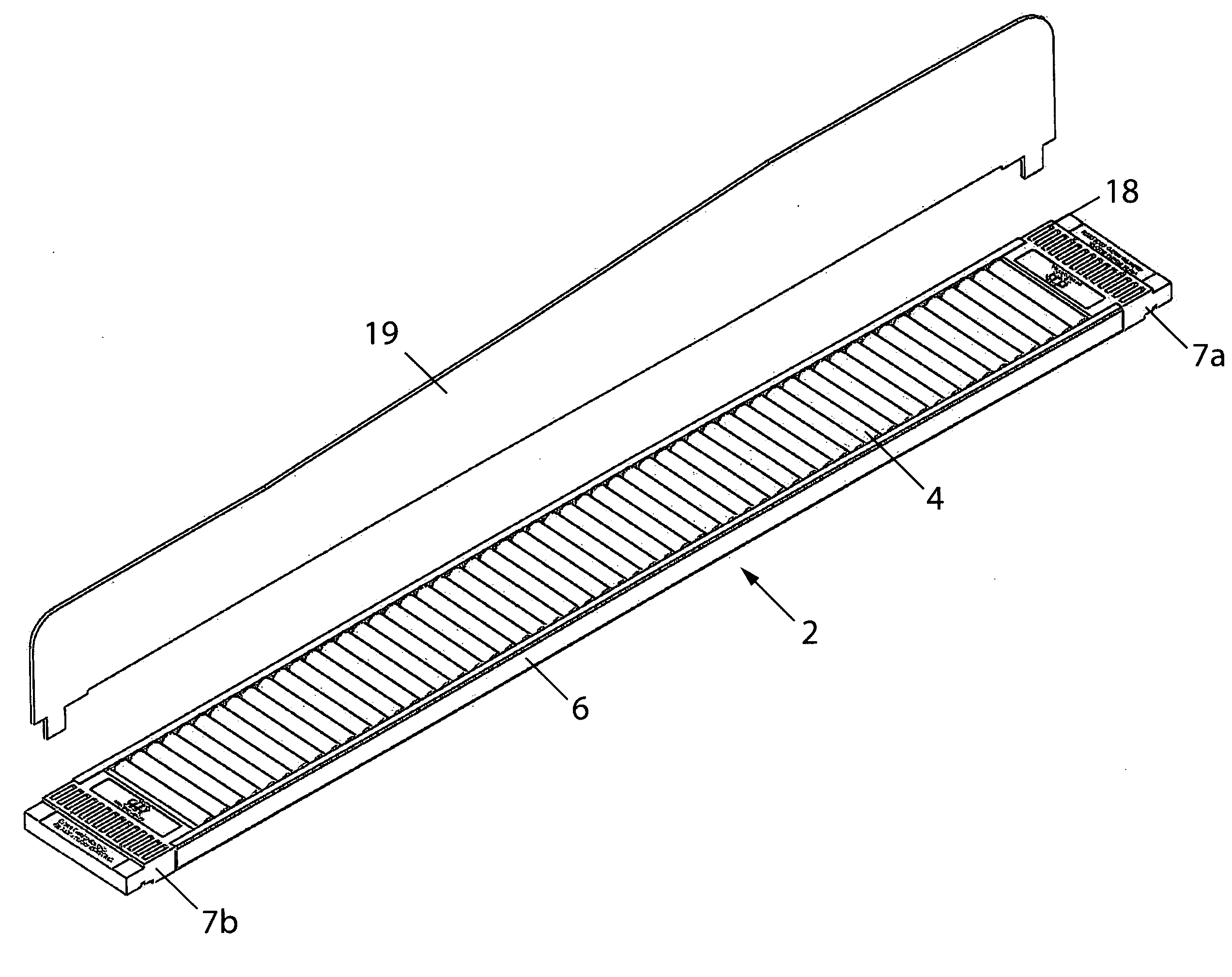
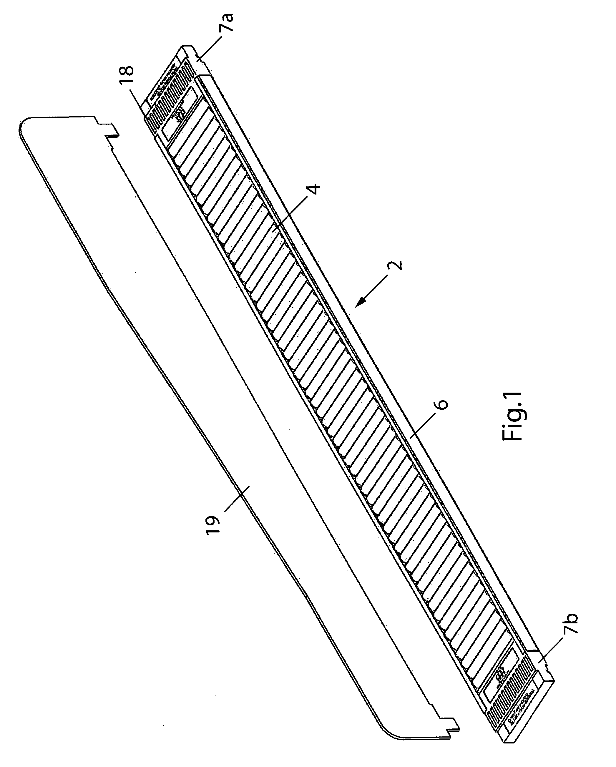
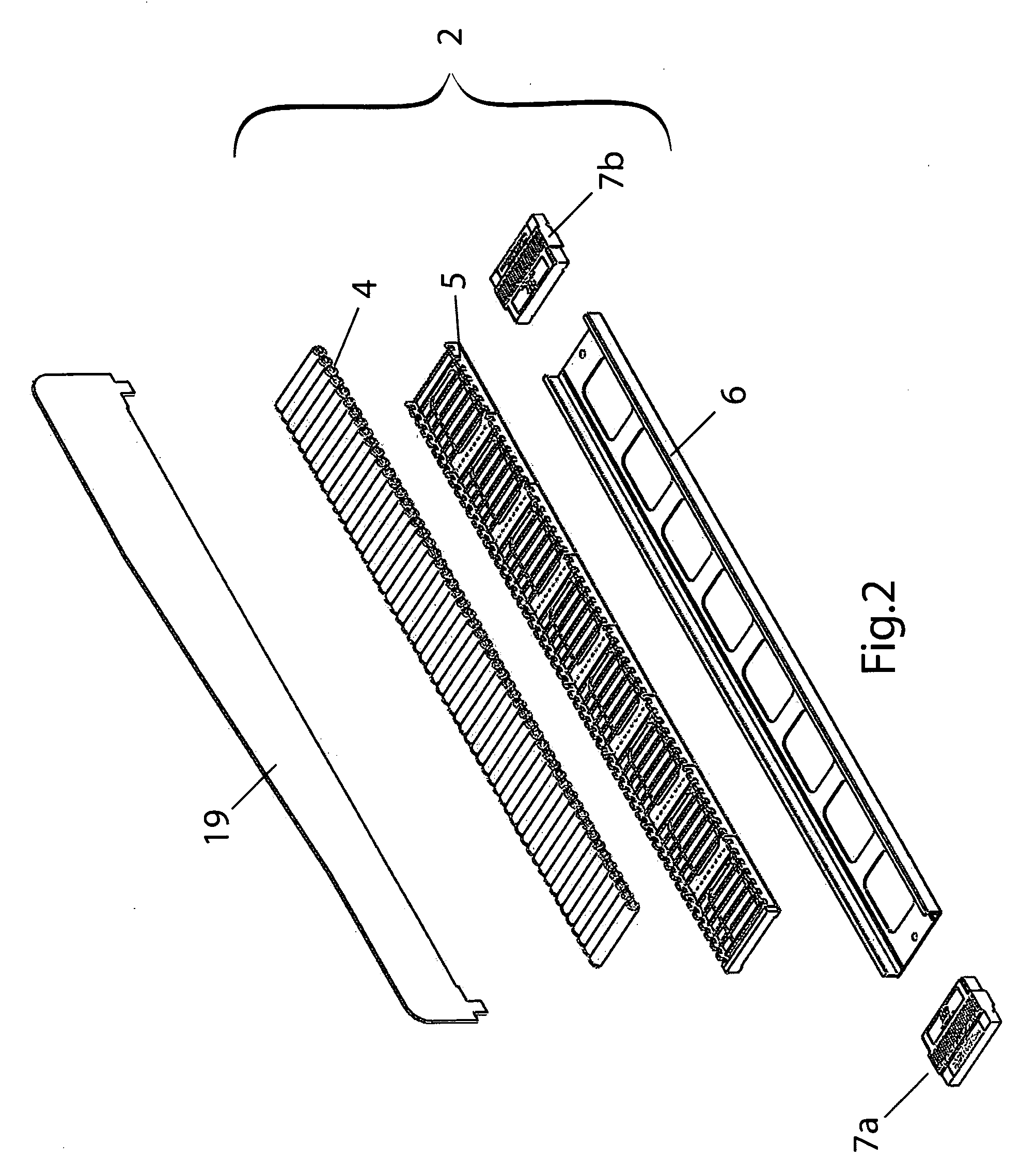
[0043]FIGS. 1 to 6 depict a roller assembly 2 in accordance with a first embodiment of the present invention. An array of such roller assemblies 2 may be used in side by side relationship to form a shelving display unit or a shelf unit 1 as shown in FIGS. 7 to 9, preferably for use in supermarket, convenience, liquor store or other retail applications.

[0044]Roller assembly or “roller track”2 comprises a set of parallel stub rollers 4 mounted on an inner casing 5 slidably engagable with an outer casing 6. The stubs 14 of rollers 4 are seated in notches 50 disposed on the sidewalls 51 of the inner casing 5 in a similar fashion to that shown in FIG. 3 of the prior mentioned U.S. Pat. No. 6,089,385 to Nozawa.

[0045]As shown in FIG. 4, inner casing 5 has a base 52 having a plurality of apertures 53 therein, and a plurality of stiffening ribs 54 spanning the apertures 53.

[0046]As shown in FIG. 5, outer casing 6 has an underside member (base) 60 from which two side members (walls) 61 upward...


PUM


Abstract

A roller assembly for use with a commodity display unit, the roller assembly comprising at least one set of parallel rollers mounted on an inner casing. Each roller is a stub roller with a stub at each end, and the inner casing has opposed side walls projecting from a base. Each side wall having a series of notches at its upper free end for respectively receiving the stubs of the stub rollers, and the inner casing with the rollers mounted thereon slidably engagable within an outer casing such that the stub rollers are restrained from being removed from their respective notches by two inwardly projecting upper flanges of the outer casing. Each upper flange projects from a respective wall member of the outer casing. The inner casing is secured within the outer casing by two end caps, each slidable engagable with the outer casing at opposed ends thereof.

Description

TECHNICAL FIELD[0001]The present invention relates to product display units having shelves that include one or more rollers to facilitate product movement on the shelves. In particular, the present invention is directed to display units and shelving therefor in which a plurality of roller assemblies are aligned in a plane and can interact with product dividers and / or other shelving features, such as a front riser, to facilitate optimum displaying and dispensing of products in retail markets and elsewhere.BACKGROUND[0002]In conventional display units with shelving it is known to move product to the front of a shelf by various means. One known arrangement is to utilise gravity feed roller assemblies in shelving display units to facilitate product movement from the rear to the front. Examples of such roller assembly shelving can be seen in the disclosures of U.S. patents, such as U.S. Pat. No. 6,089,385 to Nozawa, U.S. Pat. No. 6,409,026 to Watanabe and U.S. Pat. No. 6,497,326 to Osawa...

Claims


Application Information

Patent Timeline
IPC IPC(8): A47F7/00A47F5/00B65G13/00
CPCA47B31/00A47F5/0043A47F1/12A47B96/021
Inventor EVANS, DAVID WILLIAM
Owner HAMLON
Why Eureka
Try Eureka