Container and Method for Blowmolding a Base in a Partial Vacuum Pressure Reduction Setup

a partial vacuum pressure reduction and container technology, applied in the field of container blow molding with a base, can solve the problems of affecting the performance of the container at certain areas, affecting the ability, and plastic material is less able to flow and stretch around the protruding protruding, so as to prevent substantial net distortion of the base

Active Publication Date: 2010-06-03
CO2 PAC
View PDF4 Cites 24 Cited by
  • Summary
  • Abstract
  • Description
  • Claims
  • Application Information

AI Technical Summary

Benefits of technology

[0009]A method according to exemplary embodiments of the invention may include blowmolding a container, a base of the container having a first hinge, a first wall coupled to the first hinge, a second hinge coupled to the first wall, and a second wall coupled to the second hinge, both of the first wall and the second wall being formed extending away from an interior of the container relative to a longitudinal axis of the container, inverting the first wall about the first hinge toward the interior of the container relative to the longitudinal axis, and inverting the second wall about the second hinge toward the interior of the container relative to the longitudinal axis, wherein rigidity of the base prevents substantial net distortion of the base during inversion of the second wall.
[0011]A container having a longitudinal axis according to exemplary embodiments of the invention may include an upper portion having an opening into an interior of the container, a neck portion connected to the upper portion, a body connected to the neck portion, and a base connected to the body. The base may include a standing surface, a first wall, a second wall, the first wall and the second wall extending away from the interior of the container relative to the longitudinal axis, a first hinge positioned between the standing surface and the first wall, the first wall being rotateable about the first hinge toward the interior of the container relative to the longitudinal axis, and a second hinge positioned between the first wall and the second wall, the second wall being rotateable about the second hinge toward the interior of the container relative to the longitudinal axis, wherein rigidity of the base prevents substantial net distortion of the base during inversion of the second wall.

Problems solved by technology

One problem with stretch blowmolding is that stretching of the plastic material may affect the performance of the container at certain areas.
While the stretching of the plastic material may not cause problems for most sections of the container, it particularly affects the ability of the plastic material to form around a deep protrusion in the mold.
However, the plastic material is less able to flow and stretch around the protrusion because of the contact friction with the mold surface.
A lack of definition in the base caused by the inability of the plastic to properly form at a deep protrusion is a particular problem when one or more invertable walls are included in the base.
If the invertable walls or the surrounding areas of the base are not sufficiently rigid, inversion of the walls may deform the base, which may cause problems in the ability of the container to stably stand on a flat surface and may affect the appearance of the container.

Method used


Image

  • Container and Method for Blowmolding a Base in a Partial Vacuum Pressure Reduction Setup
  • Container and Method for Blowmolding a Base in a Partial Vacuum Pressure Reduction Setup
  • Container and Method for Blowmolding a Base in a Partial Vacuum Pressure Reduction Setup

Examples


Embodiment Construction

[0022]Exemplary embodiments of the invention are discussed in detail below. In describing the exemplary embodiments, specific terminology is employed for the sake of clarity. However, the invention is not intended to be limited to the specific terminology so selected. While specific exemplary embodiments are discussed, it should be understood that this is done for illustration purposes only. A person skilled in the relevant art will recognize that other components and configurations may be used without parting from the spirit and scope of the invention. All references cited herein are incorporated by reference as if each had been individually incorporated.

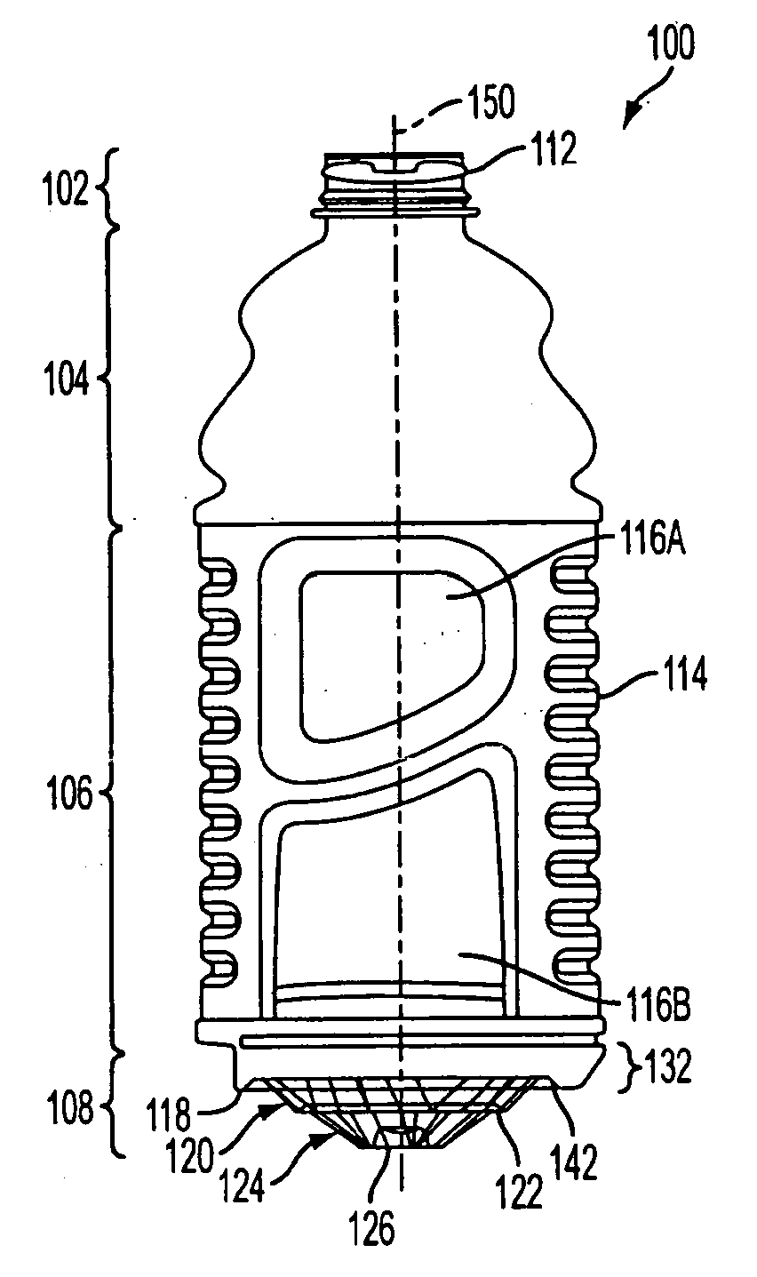
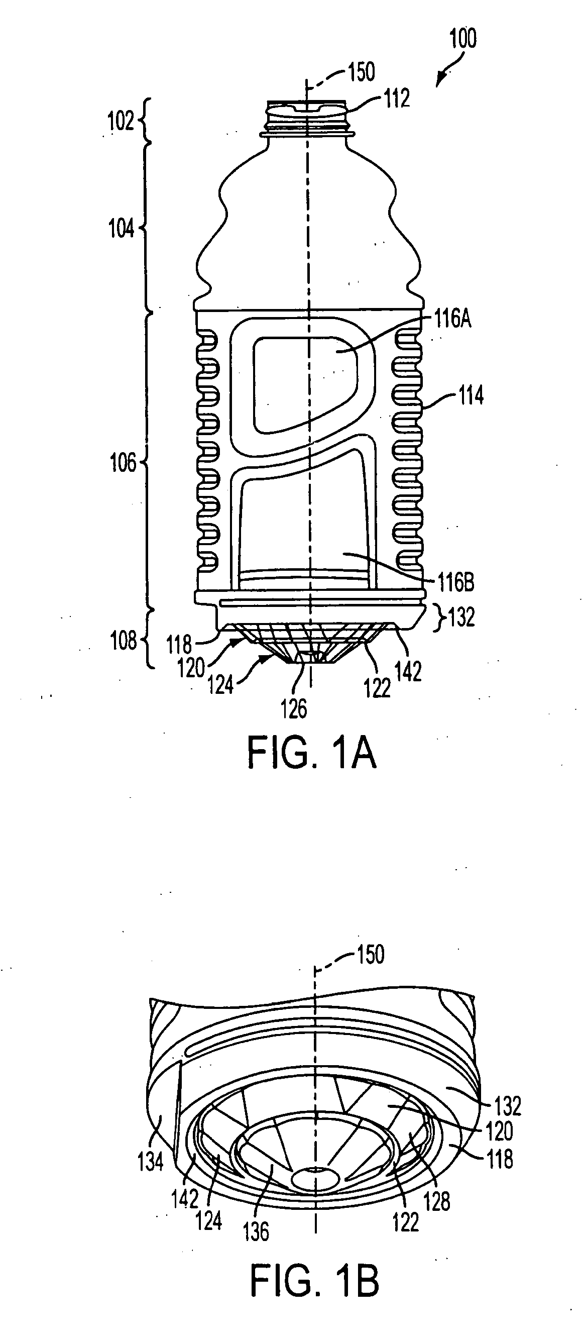
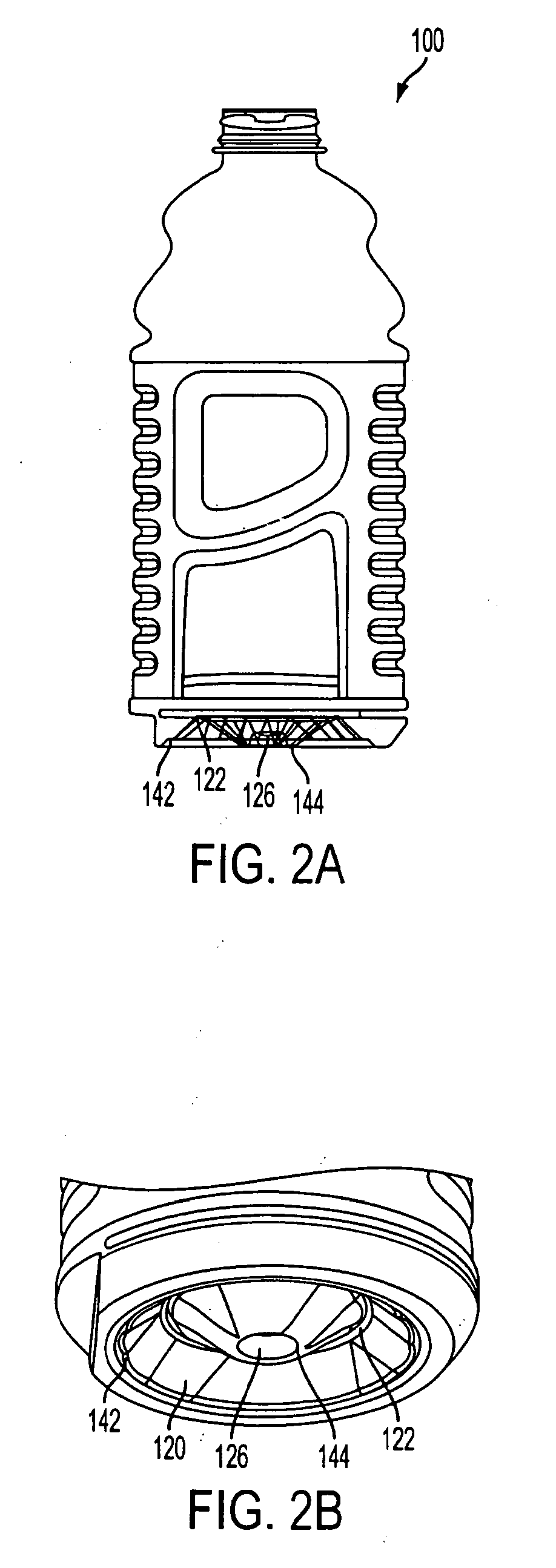
[0023]Exemplary embodiments of the present invention may generally relate to a container, a method of manufacturing a container, and a base of a container to account for the rigidity and vacuum pressure requirements experienced by a container during hot-fill processing. In an exemplary embodiment, the base of the container may incl...


PUM

PropertyMeasurementUnit
rigidityaaaaaaaaaa
mechanical forceaaaaaaaaaa
pneumatic forceaaaaaaaaaa

Abstract

A base of a container may include a standing surface, a first wall, a second wall, a first hinge, and a second hinge. The first hinge may be positioned between the standing surface and the first wall, the first wall being rotateable about the first hinge relative to a longitudinal axis of the container. The second hinge may be positioned between the first wall and the second wall, the second wall being rotateable about the second hinge relative to the longitudinal axis of the container, where rigidity of the base prevents substantial net distortion of the base during rotation of the second wall.

Description

BACKGROUND OF THE INVENTION[0001]1. Field of the Invention[0002]The invention generally relates to a method for blowmolding a container, and more particularly to a method for blowmolding a container with a base having sufficient rigidity to withstand forces experienced during inversion of a base wall.[0003]2. Related Art[0004]One method of manufacturing containers is through a process known as stretch blowmolding. In this process, a preformed parison, or preform, is prepared from a thermoplastic material, typically by an injection molding process. The preform typically includes a threaded end, which becomes the threads of the container. During stretch blowmolding, the preform is positioned between two open blow mold halves. The blow mold halves close about the preform and cooperate to provide a cavity into which the preform is blown to form the container. Once the mold is closed, a gas is forced into the perform causing it to stretch and to take the shape of the mold as the plastic ...

Claims


Application Information

Patent Timeline
Patent Type & Authority Applications(United States)
IPC IPC(8): B65D90/02
CPCB29C49/06B29C49/08B29C49/4802B65D79/005B29K2995/004B29L2031/7158B65D1/0276B29C49/541B65D2303/00B65D79/0084B29C49/42808B29C49/4283B29C2949/0715B29C49/6605
Inventor TRUDE, GREGORY
Owner CO2 PAC
Why Eureka
Try Eureka