Method for detecting strain state of tire, device for detecting strain state, and the tire

a technology of strain state and tire, which is applied in the field of tire distortion detection method, distortion detector, tire, etc., can solve the problems of difficult detection of sensors, gradual decrease of magnetic band magnetization, and difficulty in setting the magnetic force of magnetic bands at the optimal value, so as to reduce the influence of reflection and high accuracy

Inactive Publication Date: 2007-12-04
THE YOKOHAMA RUBBER CO LTD
View PDF10 Cites 10 Cited by
  • Summary
  • Abstract
  • Description
  • Claims
  • Application Information

AI Technical Summary

Benefits of technology

[0017]Time from when the scanner unit radiates a pulsed electromagnetic wave to when the scanner unit receives the reflected wave, i.e., the round-trip time of the pulsed electromagnetic wave changes according to a distance between the scanner unit and a reflector for reflecting the pulsed electromagnetic wave. Further, when a distortion of the tire changes, a difference in the round-trip time of a pulsed electromagnetic wave also changes that corresponds to each of the conductor pieces embedded in the different layers. Moreover, when a distortion of the tire changes, the conductor pieces are displaced according to the distortion and a pulsed electromagnetic wave radiated from the scanner unit is reflected to the scanner unit by a member other than the conductor pieces. Therefore, it is possible to detect a distortion of the tire by the round-trip time of a pulsed electromagnetic wave or a difference in the round-trip time of the different layers.
[0018]Besides, according to the tire distortion detecting method of the present invention, the monitoring device radiates one or more pulsed electromagnetic waves in an interval of a smaller distance or length, out of a distance between the conductor pieces adjacent to each other in the circumferential direction of the tire or the length of the conductor piece arranged in the circumferential direction of the tire, so that time measurement is conducted on all the conductor pieces and between the adjacent conductor pieces. The tire distortion detecting method of the present invention can obtain resolutions more than the number of the conductor pieces arranged in lines along the circumferential direction of the tire, thereby detecting a distortion with high accuracy.
[0019]Additionally, according to the tire distortion detecting method of the present invention, the monitoring device uses a frequency of 1 GHz or higher to radiate a pulsed electromagnetic wave. Thus, it is possible to reduce the influence of reflection made by a reinforcing metal in the tire, the reinforcing metal having a gap larger than the wavelength of the frequency.
[0028]Additionally, according to the tire distortion detector of the present invention, the pulsed electromagnetic wave is set at a frequency of 1 GHz or higher in order to reduce the influence of reflection made by the reinforcing metal in the tire, the reinforcing metal having a gap larger than the wavelength of the frequency.
[0031]According to the tire distortion detector of the present invention, when a distortion of the tire is larger than a predetermined amount, an overlap disappears between the conductor piece of the first series of conductors and the conductor piece of the second series of conductors and a gap appears between the series of conductors. The occurrence of the gap largely changes the round-trip time of a pulsed electromagnetic wave and thus it is possible to detect that a distortion of the tire has become larger than the predetermined amount.

Problems solved by technology

For example, a reduced air pressure in a tire increases the occurrence of flat tires and causes a burst at high speed, resulting in a serious accident.
However, even if tires are checked and preferred conditions are maintained for the tires, when a friction between a road surface and the tires decreases, for example, when a road surface is wet on a rainy day, skids occur under braking and move the vehicle in an unexpected direction, resulting in some accidents.
However, in conventional examples 1 and 2, since the magnetic bands are formed on the side wall when the tire is manufactured, it is quite troublesome to set the magnetic force of the magnetic band at the optimum value.
Further, when the magnetic force of the magnetic band is lower than the optimum value, the detection of the sensor becomes difficult.
Moreover, the magnetic bands may gradually decrease in magnetization due to heat generated on the tire during the running of a vehicle and the detection of the sensor may become more difficult as running time increases.

Method used


Image

  • Method for detecting strain state of tire, device for detecting strain state, and the tire
  • Method for detecting strain state of tire, device for detecting strain state, and the tire
  • Method for detecting strain state of tire, device for detecting strain state, and the tire

Examples


embodiment 1

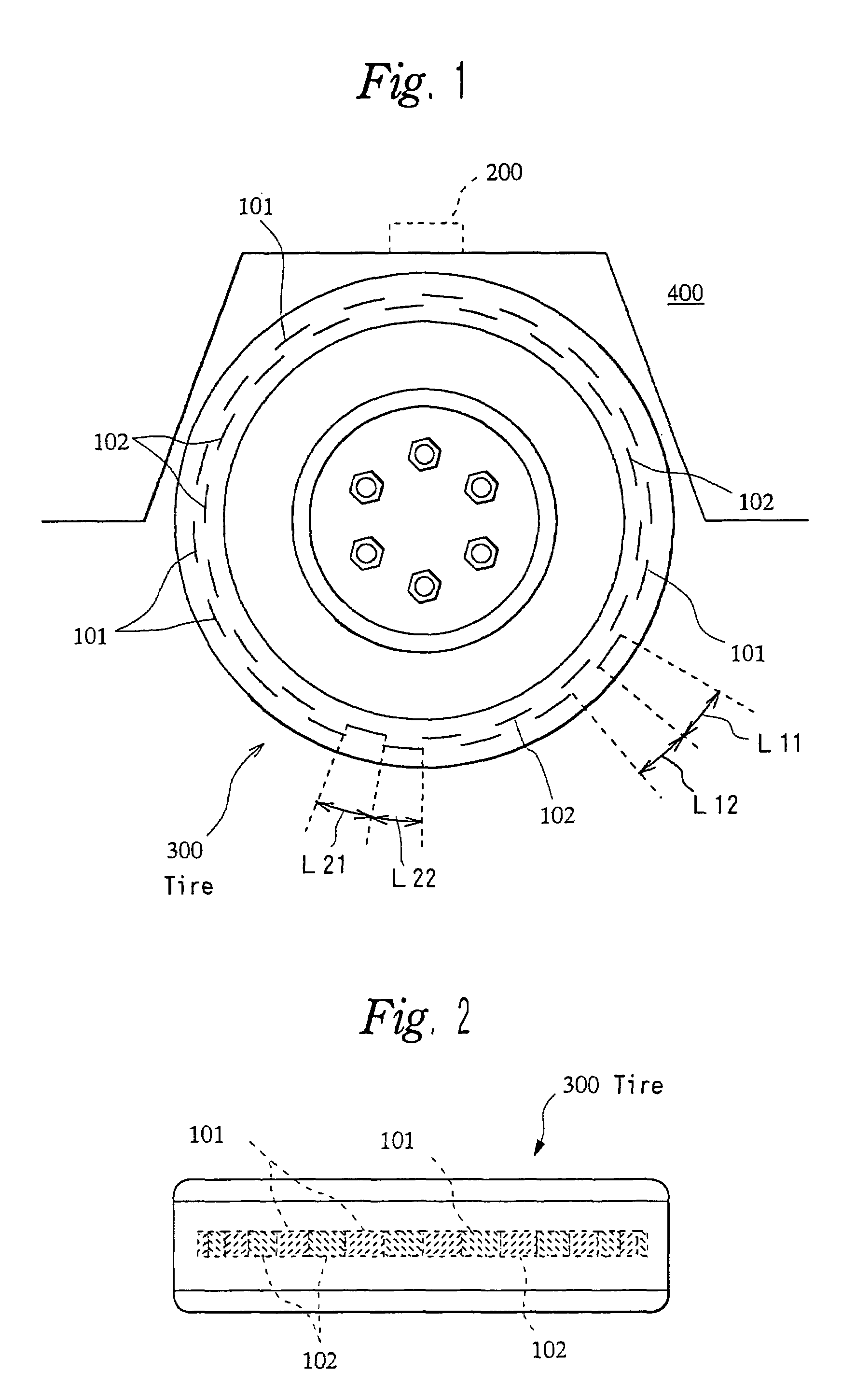
[0058]FIG. 1 is a schematic view showing a mounting state of a tire distortion detector into a vehicle of the present invention. In FIG. 1, reference numerals 101 and 102 denote metal foils (conductor piece), reference numeral 200 denotes a monitoring device, reference numeral 300 denotes a tire, and reference numeral 400 denotes a tire house.

[0059]The metal foils 101 and 102 are made of a metal such as an aluminum foil, which reflects an electromagnetic wave and is shaped like a rectangle with a predetermined width and a predetermined length.

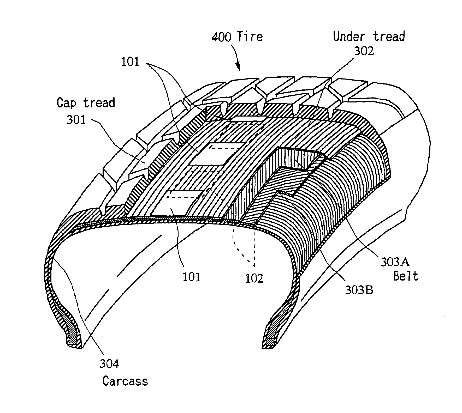
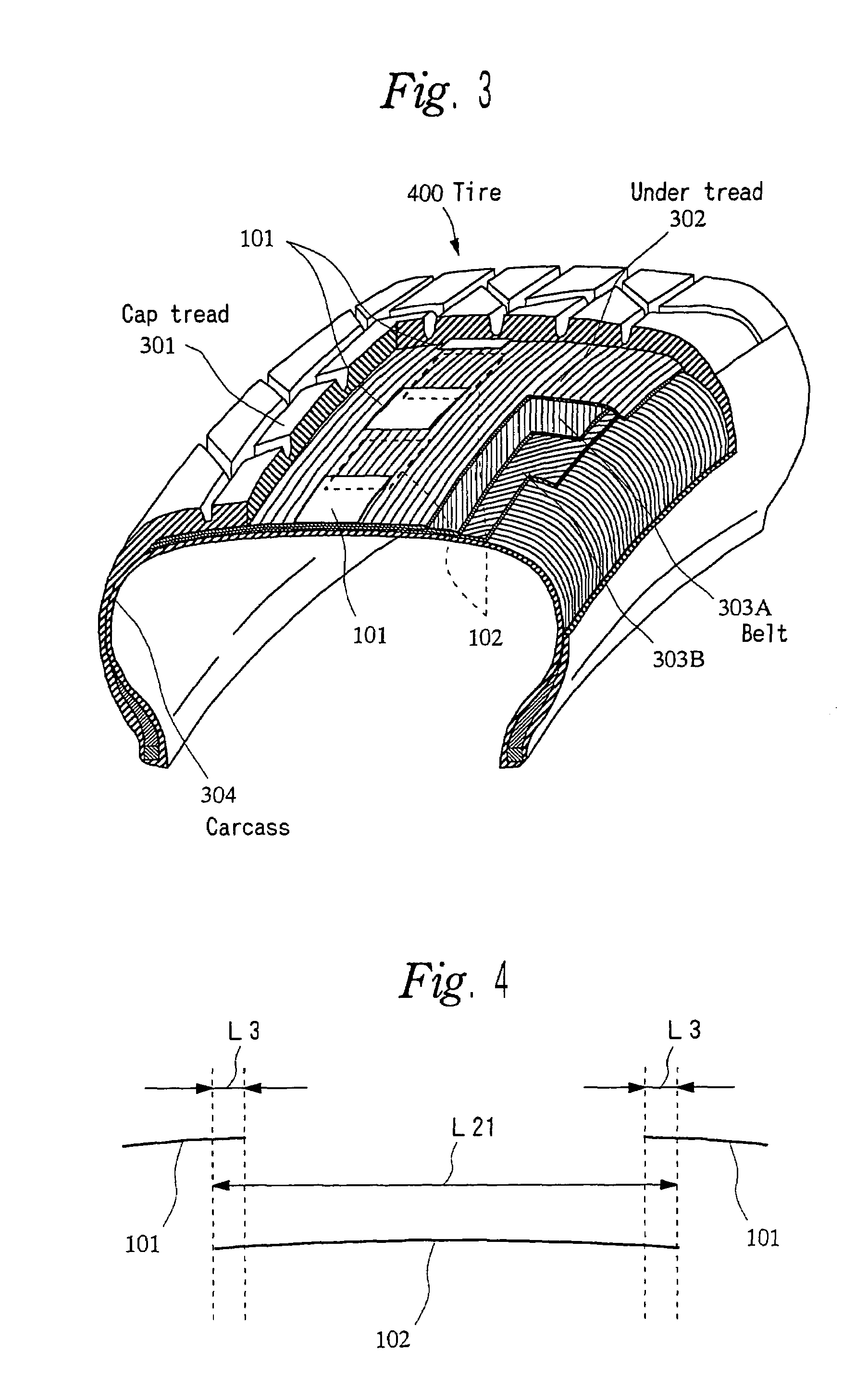
[0060]As shown in FIGS. 2 to 4, the plurality of metal foils 101 are arranged in lines at regular intervals along the circumferential direction, which has the axis of rotation of the tire 300 at the center, in a layer between a cap tread 301 and an under tread 302 so that the surfaces of the metal foils 101 are almost in parallel with the surface of the cap tread 301 and the long sides of the metal foils 101 match the circumferential direction...

embodiment 2

[0091]Further, as shown in FIG. 14, Embodiment 2 of the present invention has two monitoring devices 200A and 200B at the front and back of the top of a tire house 400. In this case, an electromagnetic wave may be radiated and received in a time-sharing manner by the monitoring devices 200A and 200B. Thus, a distortion can be detected on two points of a tire 300. Additionally a monitoring device 200 may be provided on three or more points of the tire house 400 so as to detect a distortion on three points of the tire 300.

[0092]Moreover, according to Embodiment 3 of the present invention, as shown in FIGS. 15 and 16, a tire 300A is provided instead of the tire 300 of Embodiment 1. Embodiment 3 is different from Embodiment 1 only in the tire 300A.

[0093]In the tire 300A, a series of conductors composed of a plurality of metal foils 101 and a series of conductors composed of a plurality of metal foils 102 are displaced in opposite directions along the width of the tire 300A. Besides, the...


PUM

PropertyMeasurementUnit
frequencyaaaaaaaaaa
frequencyaaaaaaaaaa
frequency bandaaaaaaaaaa

Abstract

The present invention provides a tire distortion detecting method, a distortion detector, and a tire which can reduce the occurrence of a deterioration and can be used for a control system such as a stability control system. That is, series of conductors composed of a plurality of conductor pieces 101 and 102 are provided in two different layers. The conductor pieces 101 and 102 are embedded in lines at predetermined intervals in the circumferential direction of a tire 300. A pulsed electromagnetic wave is radiated to the surfaces of metal foils 101 and 102 in the layers from a monitoring device 200 provided in a tire house 400 of a vehicle. The monitoring device 200 receives a pulsed electromagnetic wave reflected from the metal foils 101 and 102 in the layers or a member other than the metal foils. Time from the radiation of a pulsed electromagnetic wave to the reception of a reflected pulsed magnetic wave is measured repeatedly, time at which no distortion occurs on the tire 300 is stored as a reference value, and the measured time and the stored reference value are compared with each other to detect a distortion of the tire 300.

Description

TECHNICAL FIELD[0001]The present invention relates to a tire distortion detecting method, a distortion detector, and a tire thereof that detects a distortion of the tire during the running of a vehicle.BACKGROUND ART[0002]Conventionally cautions for the safe driving of a vehicle include a proper setting of an air pressure in a tire of the vehicle and attention to the wear of the tire. For example, a reduced air pressure in a tire increases the occurrence of flat tires and causes a burst at high speed, resulting in a serious accident. Therefore, drivers have to check tires on a daily basis.[0003]However, even if tires are checked and preferred conditions are maintained for the tires, when a friction between a road surface and the tires decreases, for example, when a road surface is wet on a rainy day, skids occur under braking and move the vehicle in an unexpected direction, resulting in some accidents.[0004]In order to prevent accidents caused by skids and a fast start, Anti-Lock Br...

Claims


Application Information

Patent Timeline
Patent Type & Authority Patents(United States)
IPC IPC(8): G01M17/02B60C19/00G01L17/00B60C23/06B60T8/172G01S13/88
CPCB60C11/00B60C13/001B60C19/00B60C23/06B60C23/064B60T8/1725G01M17/02B60C23/068G01S13/88B60G2204/113B60T2240/04
Inventor HATTORI, YUTAKA
Owner THE YOKOHAMA RUBBER CO LTD
Why Eureka
Try Eureka