Liquid-ejecting head, liquid-ejecting apparatus, and piezoelectric transducer

a piezoelectric transducer and liquid-ejecting head technology, which is applied in the direction of inking apparatus, device material selection, coatings, etc., can solve the problems of reducing the power supply of the device, reducing the amount of power supplied to the device, and peeling off and/or cracking of the piezoelectric transducer during operation, etc., to prevent cracking and/or peeling, large voltage, and large piezoelectric distortion

Active Publication Date: 2010-01-28
SEIKO EPSON CORP
View PDF1 Cites 9 Cited by
  • Summary
  • Abstract
  • Description
  • Claims
  • Application Information

AI Technical Summary

Benefits of technology

[0010]One advantage of this liquid-ejecting head is that the internal stress caused by the thermal expansion of the titanium oxide in the first electrode can be reduced and cracking and / or peeling can be prevented because a lattice constant of the titanium oxide therein is adjusted to that of platinum or that of a component of the piezoelectric layer. Since the relative dielectric constant of the titanium oxide therein can be adjusted to a relatively large value, a large voltage can be applied to the piezoelectric layer. Therefore, a large piezoelectric distortion can be achieved with a low driving voltage.
[0011]Another aspect of the present invention provides a piezoelectric transducer including a first electrode, a piezoelectric layer disposed on the first electrode, and a second electrode disposed on the piezoelectric layer. The first electrode contains platinum and titanium oxide and the titanium oxide with a rutile content of 76.5 to 100 mole percent. The transducer of the invention provides similar advantages to those described with reference to the liquid-ejecting head.

Problems solved by technology

One problem with the piezoelectric transducers currently known in the art, however is that the piezoelectric transducers often peel off and / or crack during operation.
This problem is worsened as the amount of power supplied to the device is reduced, creating increasing demands for liquid-ejecting heads that can eject heavy ink droplets with low driving voltage.
The problem is common not only in ink-jet recording heads and piezoelectric transducers for use in liquid-ejecting heads but also in liquid-ejecting heads which eject liquids other than ink and piezoelectric transducers for use in other devices.

Method used


Image

  • Liquid-ejecting head, liquid-ejecting apparatus, and piezoelectric transducer
  • Liquid-ejecting head, liquid-ejecting apparatus, and piezoelectric transducer
  • Liquid-ejecting head, liquid-ejecting apparatus, and piezoelectric transducer

Examples


first embodiment

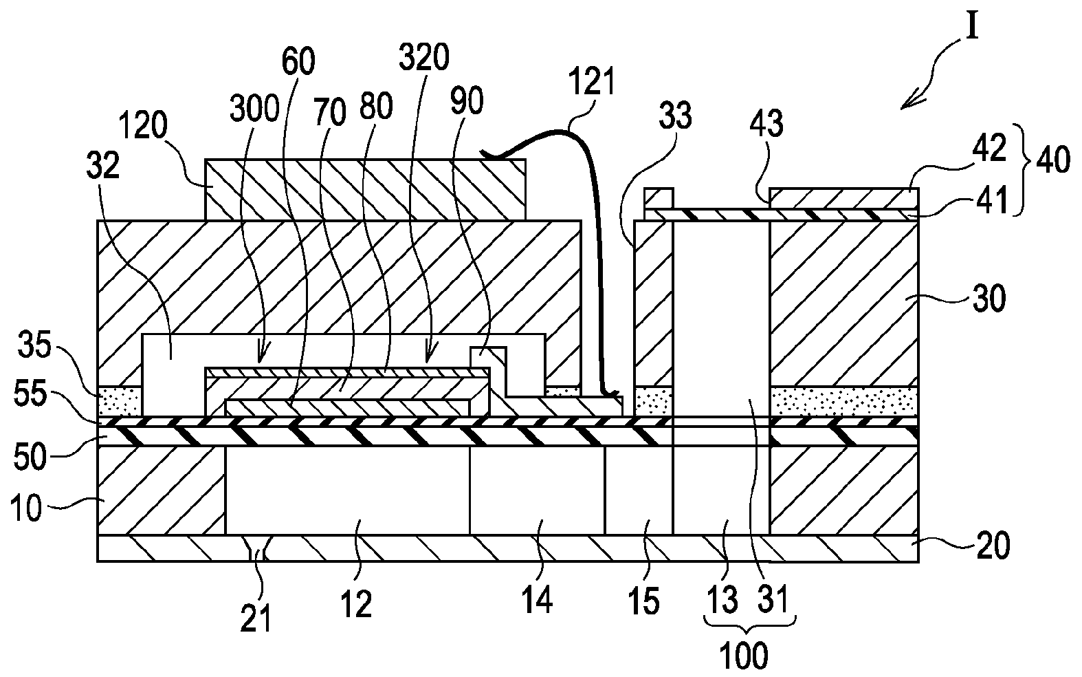
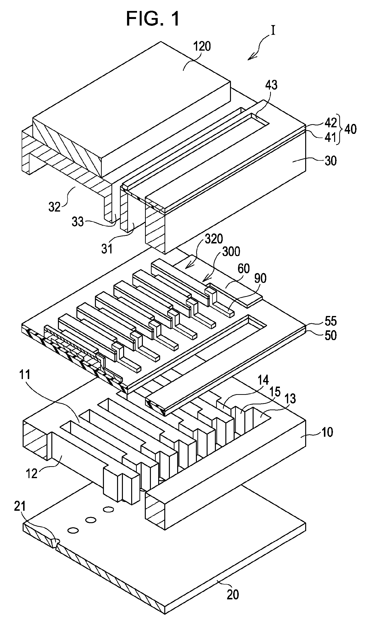
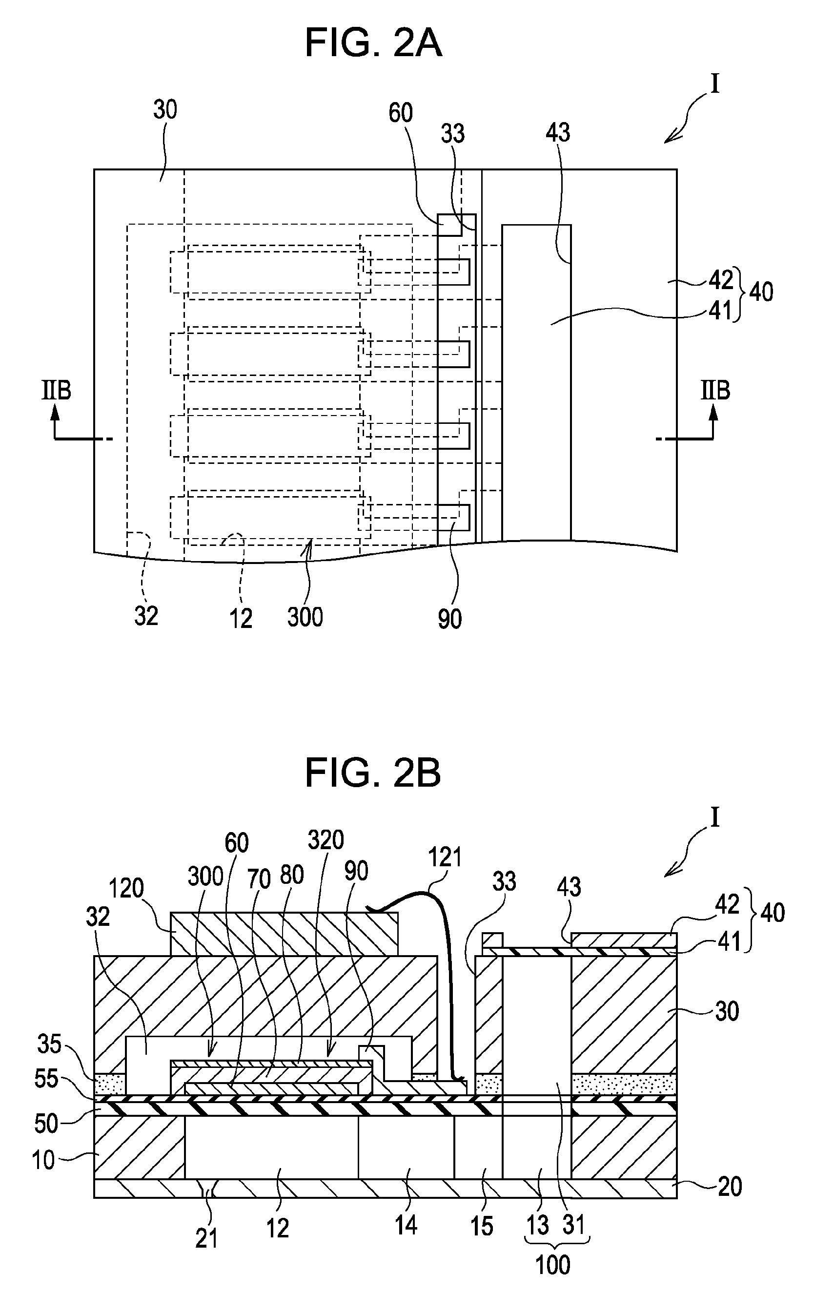
[0019]FIG. 1 shows an ink-jet recording head in exploded perspective view. The ink-jet recording head is an example of a liquid-ejecting head according to a first embodiment of the present invention. FIG. 2A is a plan view of the ink-jet recording head. FIG. 2B is a sectional view taken along the line IIB-IIB of FIG. 1.

[0020]With reference to FIG. 1, the ink-jet recording head includes a channeled substrate 10 made of single-crystalline silicon with a (110) orientation. The channeled substrate 10 carries an elastic diaphragm 50 having a thickness of about 0.5 to 2.0 μm, which is formed by thermally oxidizing a first surface of the channeled substrate 10.

[0021]The channeled substrate 10 includes separators 11, pressure-generating chambers 12, ink supply channels 14, and connection channels 15 formed by anisotropically etching a second surface of the channeled substrate 10 that is opposite to the first surface. The pressure-generating chambers 12 are separated by the separators 11 and...


PUM


Abstract

A liquid-ejecting head includes a pressure-generating chamber communicatively connected to a nozzle opening and also includes a piezoelectric transducer including a first electrode, a piezoelectric layer disposed on the first electrode, and a second electrode disposed on the piezoelectric layer. The first electrode contains platinum and titanium oxide with a rutile content of 76.5 to 100 mole percent.

Description

[0001]The entire disclosures of Japanese Patent Application No. 2008-194037, filed Jul. 28, 2008 is expressly incorporated herein by reference.BACKGROUND OF THE INVENTION[0002]1. Technical Field[0003]The present invention relates to a liquid-ejecting head which is capable of ejecting a liquid from a nozzle opening. More particularly, the present invention relates to a liquid-ejecting head, a liquid-ejecting apparatus, and a piezoelectric transducer including a first electrode, a piezoelectric layer, and a second electrode.[0004]2. Related Art[0005]Piezoelectric transducers for use in liquid-ejecting heads typically include two electrodes and a piezoelectric layer disposed between the two electrodes. The piezoelectric layer is generally made of a piezoelectric material having an electromechanical transducing function or a crystalline dielectric material. The piezoelectric transducers are used as actuators which operate in a flexural vibration mode and are mounted in liquid-ejecting h...

Claims


Application Information

Patent Timeline
Patent Type & Authority Applications(United States)
IPC IPC(8): B41J2/045B41J2/055B41J2/135B41J2/14B41J2/145H01L41/09H01L41/18H01L41/22H01L41/29
CPCB41J2/14233B41J2002/14241B41J2202/03B41J2002/14491B41J2002/14419H10N30/877H10N30/2047H10N30/8554
Inventor MOROZUMI, KOICHIKATO, JIRODENDA, SATOSHIASAOKA, ICHIRO
Owner SEIKO EPSON CORP
Why Eureka
Try Eureka