Modular LED Light Bulb

a technology of led light bulbs and modules, applied in lighting and heating apparatus, instruments, lighting support devices, etc., can solve the problems of inability to fully determine the extent of any such variability, the burden on the luminaire, and the cost of such a binning is significan

Inactive Publication Date: 2010-06-03
SIGNIFY HLDG BV
View PDF12 Cites 110 Cited by
  • Summary
  • Abstract
  • Description
  • Claims
  • Application Information

AI Technical Summary

Benefits of technology

[0008]The present invention includes an LED-based lighting device and method for making the same. The lighting device includes an LED light source mounted on a heat sink and a power adaptor. The power adaptor is configured to be interchangeable with conventional incandescent or fluorescent bulb power adapters. In one aspect of the invention, a controller provides an average current to the LED light source when power is coupled to the device via the power adaptor. The average current causes the LED light source to generate light of a predetermined standard intensity of light that is substantially independent of variations in the LED light source from device to device. In one aspect of the invention, the LED light source includes a plurality of LEDs connected in series, the LEDs are bonded to the heat sink and connected to one another in series by wire bonds and to conducting traces on the heat sink.

Problems solved by technology

Unfortunately, the performance of an LED depends critically on the manner in which the LED is packaged.
While the manufacturer of the packaged LEDs can “bin” the final packaged LEDs to provide products having more uniformity, the cost of such binning is significant.
Hence, until the packages are assembled in the final luminaire, the extent of any such variability cannot be fully determined.
This places the burden on the luminaire manufacturer who must have the facilities needed to test the packaged LEDs in that manufacturer's luminaire, since a standardized part is not available that provides a light source with a standardized output in terms of intensity when connected to a standard AC electrical outlet.
This increases the capital investment needed to establish the production line.

Method used


Image

  • Modular LED Light Bulb
  • Modular LED Light Bulb
  • Modular LED Light Bulb

Examples


Embodiment Construction

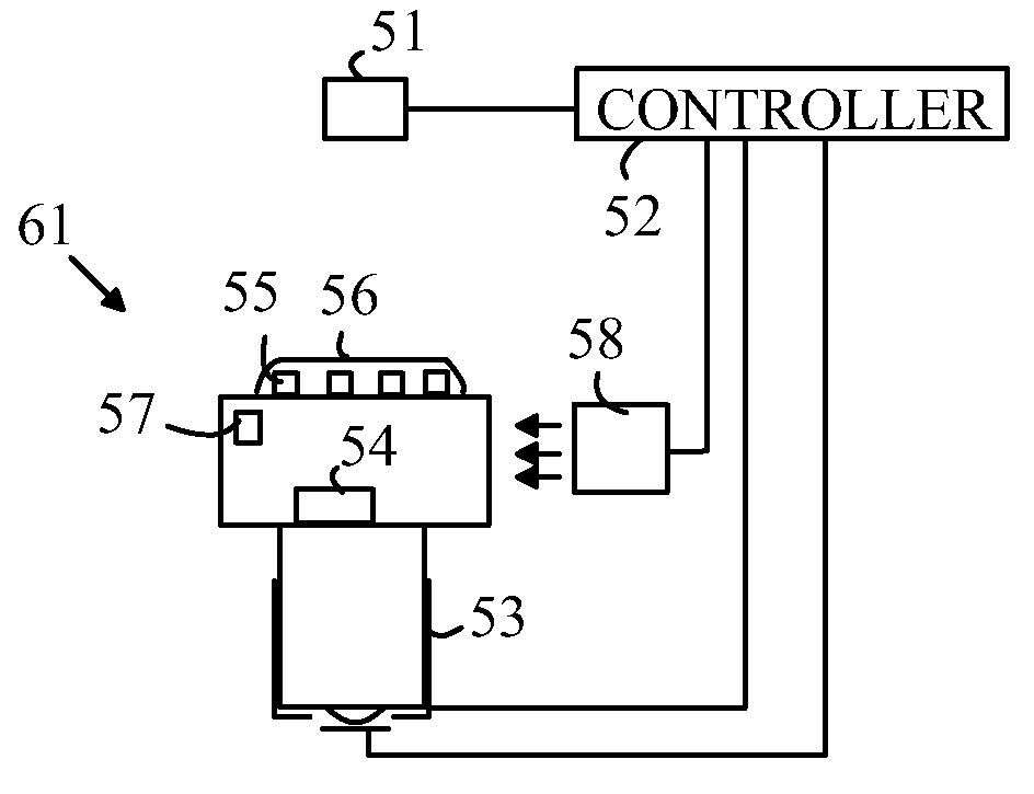
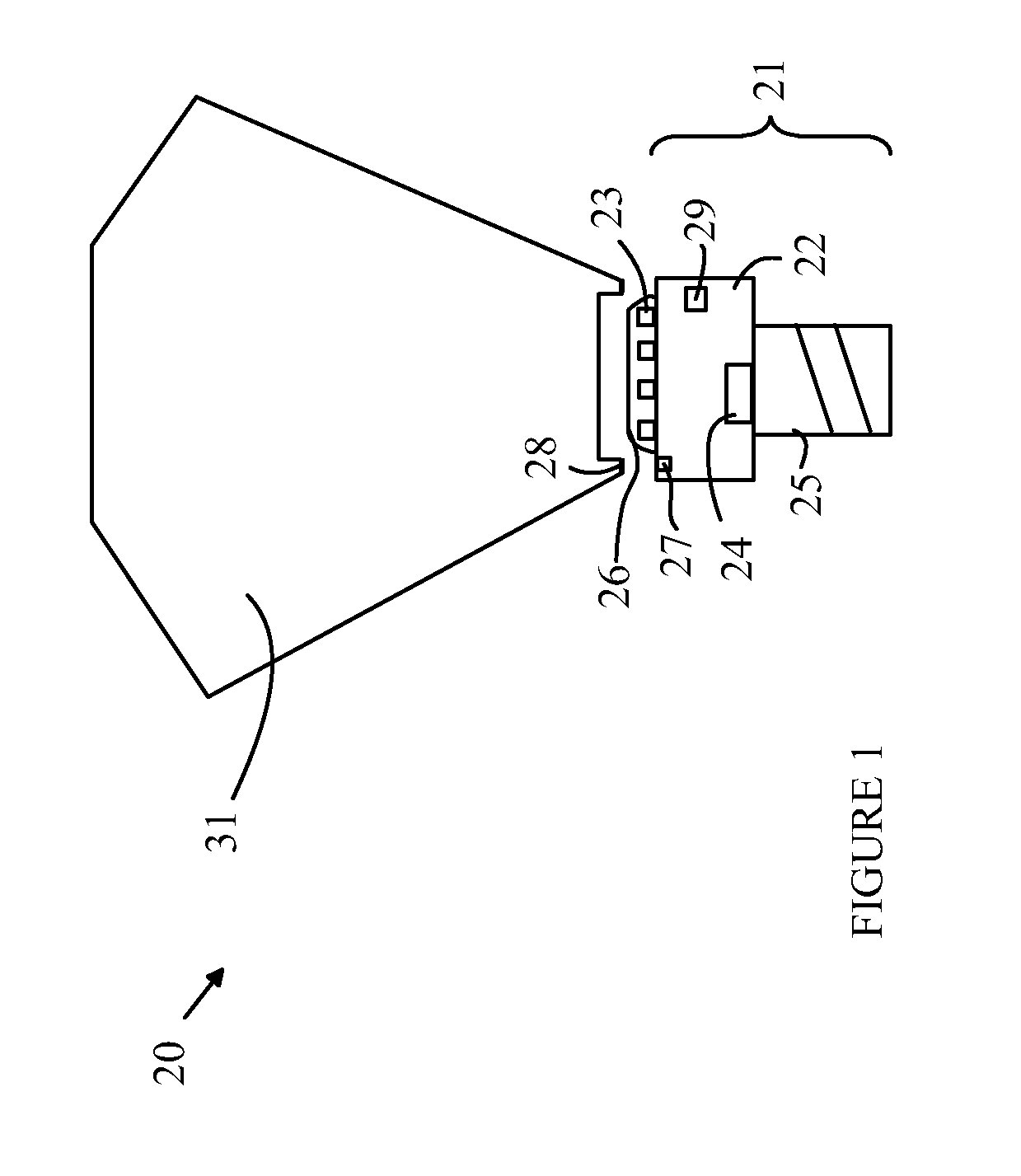
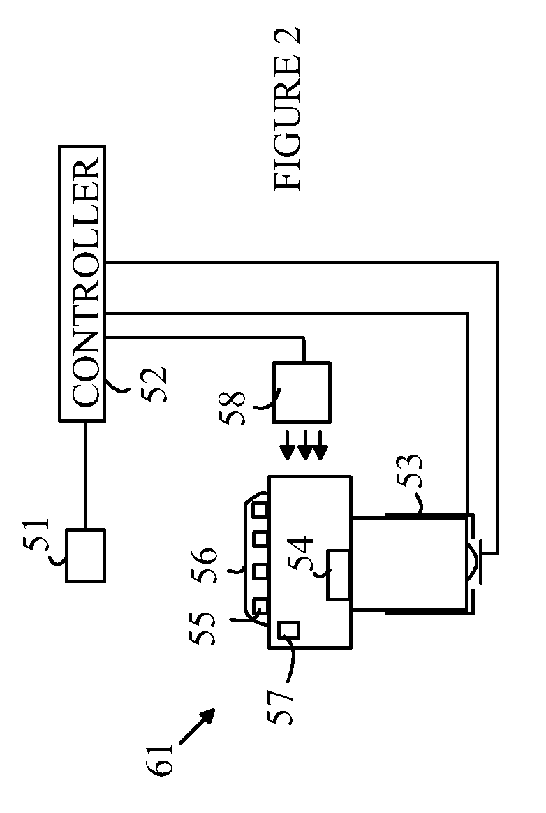
[0018]The manner in which the present invention provides its advantages can be more easily understood with reference to FIG. 1 which is a cross-sectional view of lighting device 20 with a light base unit 21 according to the present invention that can be connected to any of a number of light diffusers 31. Base unit 21 includes a heat sink 22 on which a plurality of LEDs 23 are mounted. The number of LEDs depends on the particular application and power rating of the base unit. A controller 24 powers the LEDs. To simplify the drawings, the connections between controller 24 and the LEDs have been omitted from the drawing. A standard connector 25 such as a screw in bulb connector is used to connect base unit 21 to a conventional light socket. Non-screw-in connectors such as “bayonet” connectors can also be utilized.

[0019]As noted above, the LEDs can vary in their light output due to variations in the manufacturing process utilized to fabricate the LEDs. In addition, in some applications,...


PUM

PropertyMeasurementUnit
wavelengthaaaaaaaaaa
AC voltageaaaaaaaaaa
light intensityaaaaaaaaaa

Abstract

An LED-based lighting device and method for making the same are disclosed. The lighting device includes an LED light source mounted on a heat sink, a power adaptor, and a controller. The power adaptor is configured to be interchangeable with a conventional incandescent bulb power adapter. The controller provides an average current to the LED light source when power is coupled to the device via the power adaptor. The average current causes the LED light source to generate light of a predetermined standard intensity that is substantially independent of variations in the LED light source from device to device. In one aspect of the invention, the LED light source includes a plurality of LEDs connected in series, the LEDs are bonded to the heat sink and connected to one another in series by wire bonds and to conducting traces on the heat sink.

Description

BACKGROUND OF THE INVENTION [0001]Light emitting diodes (LEDs) are attractive candidates for replacing conventional light sources such as incandescent lamps and fluorescent light sources. The LEDs have higher light conversion efficiencies than incandescent lamps and longer lifetimes than both types of conventional light sources. Furthermore, the conversion efficiencies of LEDs continue to improve.[0002]An LED produces light in a relatively narrow spectral band. Hence, to produce a light source having an arbitrary color, a compound light source having multiple LEDs is typically utilized or part of the light from a single LED must be converted to light of a second wavelength, which is mixed with the light from the original LED. For example, an LED-based white light source that provides an emission that is perceived as white by a human observer can be constructed by combining light from arrays of red, blue, and green emitting LEDs that are generating the correct intensity of light at e...

Claims


Application Information

Patent Timeline
Patent Type & Authority Applications(United States)
IPC IPC(8): H05B39/04F21V29/00
CPCF21V23/0442F21Y2101/02H05B33/0803H05B33/0815F21K9/135F21K9/56F21V29/90F21V17/164F21V23/005F21V3/0481F21V23/0457F21V29/74F21V29/85F21V17/002H01L2924/181H01L2224/48091H01L2224/48137H01L2224/73265F21K9/232F21K9/64F21Y2115/10F21K9/238F21V3/12H05B45/22H05B45/00H01L2924/00014H01L2924/00012H05B45/37
Inventor HASNAIN, GHULAM
Owner SIGNIFY HLDG BV
Why Eureka
Try Eureka