Method and apparatus for scaling the average current supply to light-emitting elements

a technology of average current supply and light-emitting elements, applied in the field of light-emitting, can solve the problems of low efficiency, large number of components, and low work efficiency

Active Publication Date: 2009-01-27
SIGNIFY HLDG BV
View PDF10 Cites 78 Cited by
  • Summary
  • Abstract
  • Description
  • Claims
  • Application Information

AI Technical Summary

Problems solved by technology

Practically however, this only works well if the forward voltage of each LED is nearly identical, otherwise different values of resistors must be chosen for each different LED to prevent current hogging by any one LED in this parallel configuration.
This use of resistors can also induce large losses thus reducing the overall efficiency of the circuit.
These techniques however, typically use a large number of components and have a low efficiency.
Another means to address forward voltage differences in parallel strings is through forward voltage binning which is not necessarily practical in terms of the additional step during the production process.
This procedure can additionally result in wasted parts.
This disparity in forward voltage requirements can be compounded when several of these LEDs are stacked in series, with the result being that parallel strings of the same number of LEDs can have large forward voltage drops.
As a result, the LED strings with a lower forward voltage requirement will have excess voltage, which will result in excess power dissipated by the components in series with the LEDs that are used to limit the current across the LED string with the lower forward voltage drop.
If this form of dissipation was not provided, excess current will flow through the LED string with the lower forward voltage drop which can overdrive the LED string and result in LED damage.
This configuration has two problems.
Secondly, firmware can become more complicated since different LED strings must be driven with different duty cycles to achieve the same level of effective dimming, thereby resulting in a requirement for custom calibration factors to be determined for each LED string for storage in EEPROM (electrically erasable programmable read-only memory), for example.
These problems would also typically apply to any other digital control method known in the art that could be used to vary LED brightness, for example, Pulse Code Modulation (PCM).

Method used


Image

  • Method and apparatus for scaling the average current supply to light-emitting elements
  • Method and apparatus for scaling the average current supply to light-emitting elements
  • Method and apparatus for scaling the average current supply to light-emitting elements

Examples


Embodiment Construction

Definitions

[0020]The term “light-emitting element” is used to define any device that emits radiation in any region or combination of regions of the electromagnetic spectrum for example the visible region, infrared and / or ultraviolet region, when activated by applying a potential difference across it or passing a current through it, for example. Examples of light-emitting elements include semiconductor, organic, polymer, phosphor-coated or high-flux light-emitting diodes or other similar devices as would be readily understood.

[0021]The term “power source” is used to define a means for providing power to an electronic device and may include various types of power supplies and / or driving circuitry.

[0022]Unless defined otherwise, all technical and scientific terms used herein have the same meaning as commonly understood by one of ordinary skill in the art to which this invention belongs.

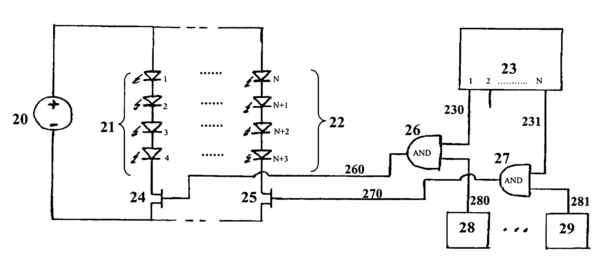
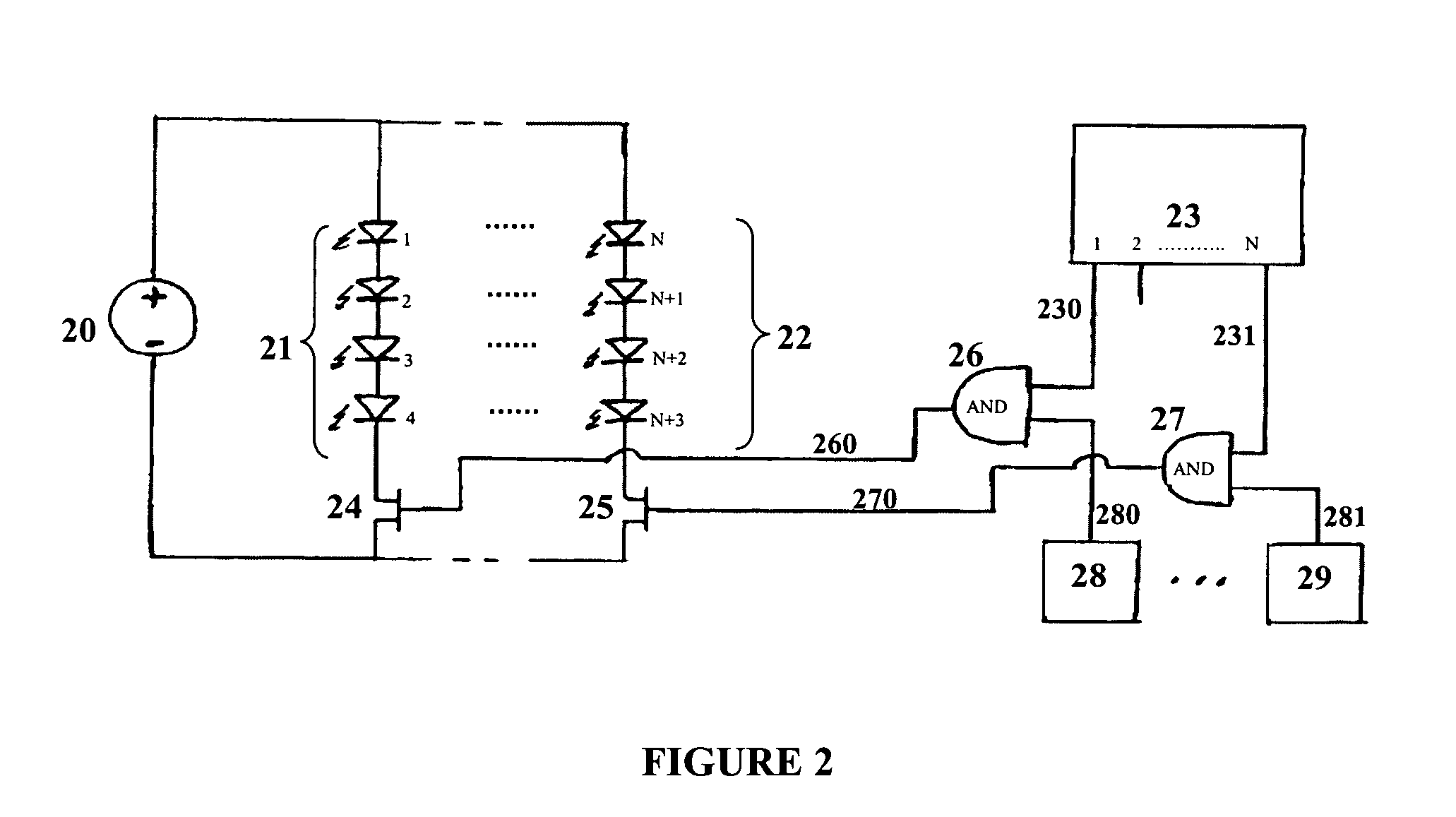
[0023]The present invention provides a method and apparatus for scaling the average drive current sup...


PUM


Abstract

The present invention provides a method and apparatus for scaling the average drive current supplied to a light-emitting element or string thereof by coupling a scaling signal to an original control signal thereby generating an effective control signal for control of the light-emitting element(s). The scaling signal can be a modulated signal, for example a Pulse Width Modulation (PWM) signal, Pulse Code Modulation (PCM) signal, or other signal and modifies the original control signal to produce an effective control signal. The effective control signal is subsequently used to control the supply of power to the light-emitting element(s) from a power source via a switching device. The effective control signal essentially modifies the ON time of the light-emitting element(s), thereby modifying the average drive current passing through the light-emitting element(s). The scaling signal is coupled to the original control signal by a coupling mechanism, thereby enabling the modification of the original control signal by the scaling signal forming the effective control signal.

Description

CROSS-REFERENCE TO RELATED APPLICATIONS[0001]This application claims the benefit of U.S. Provisional Patent Application No. 60 / 600,825, filed Aug. 12, 2004, which is hereby incorporated herein by reference.FIELD OF THE INVENTION[0002]The present invention relates to the field of lighting and more specifically to scaling of the average current supplied to light-emitting elements.BACKGROUND[0003]Recent advances in the development of semiconductor and organic light-emitting diodes (LEDs and OLEDs) have made these solid-state devices suitable for use in general illumination applications, including architectural, entertainment, and roadway lighting, for example. As such, these devices are becoming increasingly competitive with light sources such as incandescent, fluorescent, and high-intensity discharge lamps.[0004]An advantage of LEDs is that their turn-on and turn-off times are typically less than 100 nanoseconds. The average luminous intensity of an LED can therefore be controlled usi...

Claims


Application Information

Patent Timeline
Patent Type & Authority Patents(United States)
IPC IPC(8): H05B37/00H05B44/00
CPCG09G3/2018G09G3/32H05B33/0818H05B33/0827H05B33/0845G09G2300/06H05B45/46H05B45/10
Inventor JUNGWIRTH, PAULTOMA, ION
Owner SIGNIFY HLDG BV
Why Eureka
Try Eureka