
Method and apparatus for sensing flash memory using delta sigma modulation

a technology of delta sigma and flash memory, applied in the field of methods and apparatus for sensing flash memory using delta sigma modulation, can solve the problems of loss of information previously stored by the integrator, relatively slow settling time of reference voltage, etc., and achieve accurate analog comparison and high precision circuitry

Active Publication Date: 2006-11-09
MICRON TECH INC
View PDF6 Cites 81 Cited by
  • Summary
  • Abstract
  • Description
  • Claims
  • Application Information

AI Technical Summary

Benefits of technology

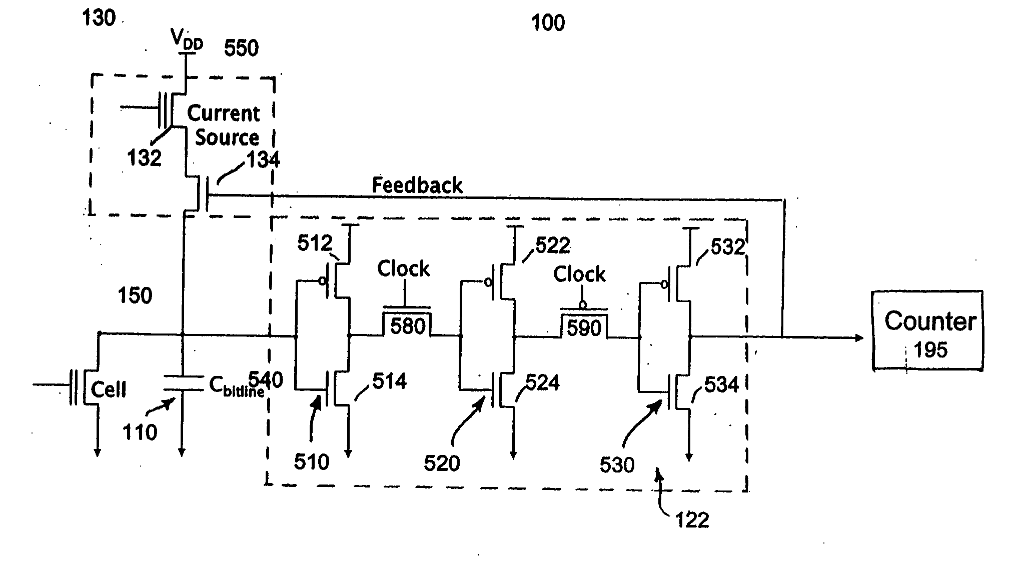
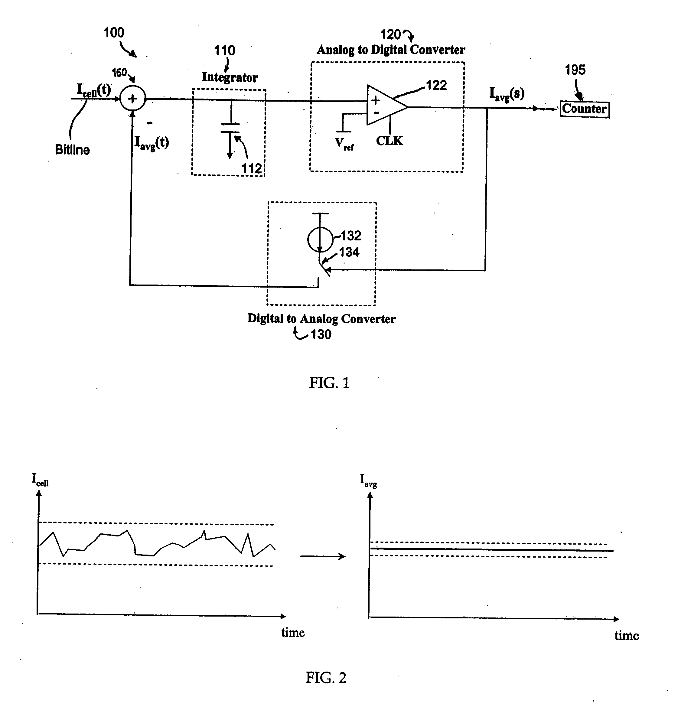
The invention provides a way to accurately sense the current in flash memory cells using a simple method and apparatus. This is done by using a sense amplifier circuit that operates using delta sigma modulation. The process involves applying an input current and a feedback output current to a summer, integrating the resulting summer output over time by an integrator, passing the integrator output to a clocked comparator, outputting a comparator output which controls a feedback circuit that keeps the integrator's voltage at the same level as a reference voltage, and outputting a digital average current in the form of pulses to a counter. The feedback is used to determine the average value of the flash cell current over a pre-determined amount of time, averaging out errors due to noise. The integrator is a capacitor that is charged by connection to a current source that deposits a set amount of charge to the capacitor, which integrates current over the entire sensing time, rather than over just one discharge cycle. The use of delta sigma modulation in the sense amplifier alleviates the need for high precision circuitry that is necessary to provide noise immunity and accurate analog comparisons in conventional sense amplifiers.

Problems solved by technology

Since the VDD supply essentially provides an infinite amount of charge, each time the integrator is charged, the information previously stored by the integrator is lost.
In addition, there is a relatively slow settling time of the reference voltage due to the large capacitive loading on the reference current generator / mirror circuit when a large number of sense amplifiers are used.

Method used


Image

  • Method and apparatus for sensing flash memory using delta sigma modulation
  • Method and apparatus for sensing flash memory using delta sigma modulation
  • Method and apparatus for sensing flash memory using delta sigma modulation

Examples


Embodiment Construction

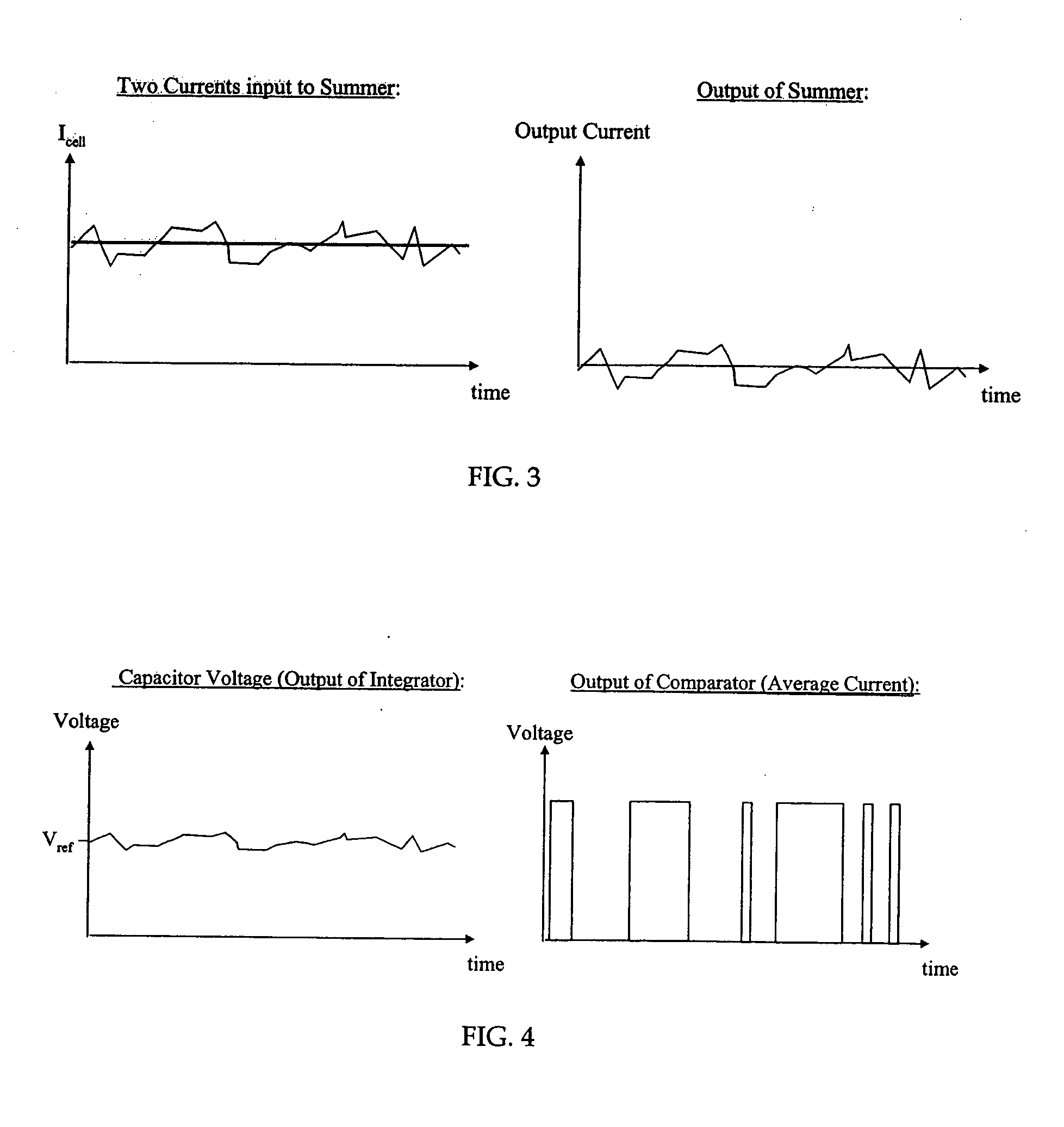
[0024]FIG. 1 illustrates a block diagram of a sense amplifier circuit 100 constructed in accordance with an exemplary embodiment of the invention. The circuit 100 comprises an integrator 110, an analog-to-digital converter 120 (“ADC”), and a digital-to-analog converter 130 (“DAC”). For this illustrated embodiment, the integrator 110 is implemented as a capacitor 112, the ADC 120 is implemented as a simple clocked comparator 122, and the DAC 130 is implemented as a current source 132 and switch 134 controlled by the output of the ADC 120. Referring also to FIGS. 2 and 3, the inputs to the circuit 100 are the flash cell current Icell and the previous average cell current output Iavg from the DAC 130, both of which are shown in FIG. 2. The currents Icell, Iavg, are combined at a summer 150. FIG. 2 illustrates examples of cell current input to the sense amplifier of the exemplary invention and the desired current output. The flash cell current Icell varies with time due to adjacent circ...


PUM


Abstract

A simple method and device for accurately measuring flash memory cell current. The sensing scheme comprises an integrator, an analog to digital converter, and a digital to analog converter. The method comprises the acts of applying an input current and a feedback output current to a summer, integrating the resulting summer output over time, passing the integrated output to a clocked comparator, outputting a comparator output which controls a feedback circuit that keeps the integrator's voltage at the same level as a reference voltage, and outputting a digital average current to a counter. Delta sigma modulation (averaging) is employed to cancel out noise that would otherwise affect the cell current measurement.

Description

[0001] The invention relates generally to semiconductor memory consisting of floating gate devices such as flash, electrically programmable read-only memory (EPROM), electrically eraseable programmable read-only memory (EEPROM) and flash EEPROM, and specifically to circuits and techniques for reading and sensing their memory states. BACKGROUND OF THE INVENTION [0002] Non-volatile memories, such as EEPROM or flash memories, are widely used in portable devices including devices lacking a mass data storage device and a fixed source of power, such as cellular phones, handheld personal computers (PCs), portable music players and digital cameras. These memories can be erased and have new data written or “programmed” into their memory cells for long term storage. Flash memories are also commonly used to hold boot code in PC's, as well as used in servers, networks, and set top boxes. [0003] A floating gate memory cell employs a floating conductive gate, within a transistor structure, but un...

Claims


Application Information

Patent Timeline
Patent Type & Authority Applications(United States)
IPC IPC(8): G11C16/06
CPCG11C7/062G11C7/067G11C2207/063G11C16/26G11C11/5642
Inventor TAYLOR, JENNIFERBAKER, R. J.
Owner MICRON TECH INC
Learn More