System and method for a constant current source LED driver

a technology of constant current source and led driver, which is applied in the direction of electric variable regulation, process and machine control, instruments, etc., can solve the problems of large current change, damage or destruction of leds

Active Publication Date: 2010-07-01
STMICROELECTRONICS SRL
View PDF19 Cites 79 Cited by
  • Summary
  • Abstract
  • Description
  • Claims
  • Application Information

AI Technical Summary

Problems solved by technology

Therefore, a small change in voltage can lead to a large change in current.
If the maximum voltage rating is exceeded by a small amount the current rating may be exceeded by a large amount, potentially damaging or destroying the LED.

Method used


Image

  • System and method for a constant current source LED driver
  • System and method for a constant current source LED driver
  • System and method for a constant current source LED driver

Examples


Embodiment Construction

[0024]FIGS. 1 through 16, discussed below, and the various embodiments used to describe the principles of the present disclosure in this patent document are by way of illustration only and should not be construed in any way to limit the scope of the disclosure. Those skilled in the art will understand that the principles of the present disclosure may be implemented in any suitably arranged LED system.

[0025]In order to prevent problems associated with exceeding the maximum voltage requirements, a typical solution is to use constant current power supplies, or driving the LED at a voltage much below the maximum rating. Since few household power sources (batteries, mains) are constant current sources, most LED fixtures must include a power converter.

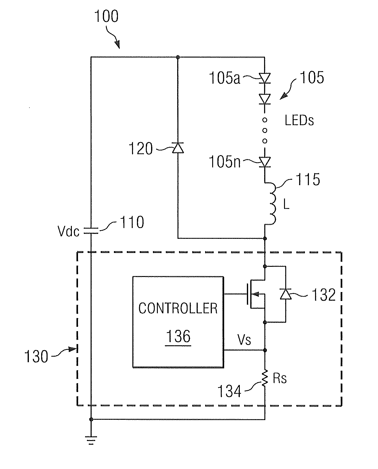
[0026]FIG. 1 illustrates an example LED system with a buck converter. The embodiment of the LED system with buck converter 100 shown in FIG. 1 is for illustration only. Other embodiments of the LED system with buck converter 100 could be use...


PUM


Abstract

A system and method for providing a constant current source driver for a light emitting diode string. The converter includes a current sensor that derives feedback signal corresponding to a peak current through the light emitting diode string. The feedback signal is used by a controller to vary a duty cycle of the controller to regulate the average current. The controller is operable to regulate the average current as the number of light emitting diodes is increased and/or decreased.

Description

CROSS-REFERENCE TO RELATED APPLICATION(S) AND CLAIM OF PRIORITY[0001]The present application is related to U.S. Provisional Patent No. 61 / 204,070, filed Dec. 31, 2008, entitled “CONSTANT CURRENT SOURCE LED DRIVE”. Provisional Patent No. 61 / 204,070 is assigned to the assignee of the present application and is hereby incorporated by reference into the present application as if fully set forth herein. The present application hereby claims priority under 35 U.S.C. §119(e) to U.S. Provisional Patent No. 61 / 204,070.TECHNICAL FIELD OF THE INVENTION[0002]The present application relates generally to light emitting diode drivers and, more specifically, to a constant current source for light emitting diodes.BACKGROUND OF THE INVENTION[0003]A Light Emitting Diode (LED) is an electronic light source. Like a normal diode, the LED consists of a chip of semiconducting material impregnated, or doped, with impurities to create a p-n junction. As in other diodes, current flows easily from the p-side, ...

Claims


Application Information

Patent Timeline
Patent Type & Authority Applications(United States)
IPC IPC(8): H05B37/02
CPCH05B33/0815H05B33/0851Y02B20/347H05B45/10Y02B20/30H05B45/385H05B45/375H05B45/14
Inventor SHAO, JIANWENLO GIUDICE, JOHN S.STAMM, THOMAS A.
Owner STMICROELECTRONICS SRL
Why Eureka
Try Eureka