
Circuits and methods for powering light sources

a technology of circuits and light sources, applied in the direction of electric variable regulation, process and machine control, instruments, etc., can solve the problems of system cost increase, system power efficiency reduction, and system solution not being suitable for systems requiring relatively large led currents

Active Publication Date: 2011-10-13
O2 MICRO INT LTD
View PDF1 Cites 86 Cited by
  • Summary
  • Abstract
  • Description
  • Claims
  • Application Information

AI Technical Summary

Benefits of technology

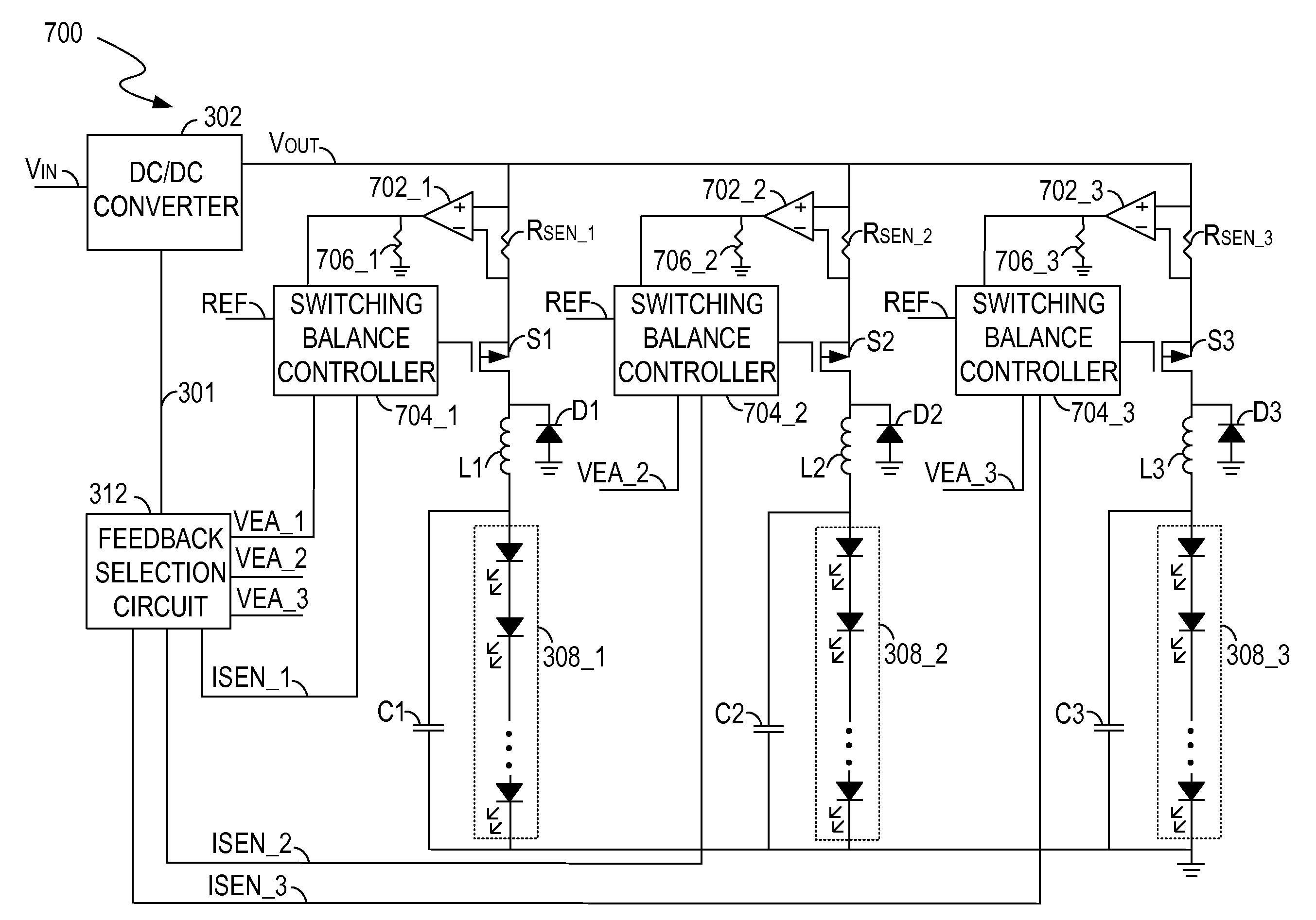
[0005]A driving circuit for powering a plurality of light-emitting diode (LED) light sources includes a power converter and a plurality of current balance controllers. The power converter receives an input voltage and provides a regulated voltage to the LED light sources. The current balance controllers coupled to the power converter control a plurality of currents through the LED light sources respectively. The current balance controllers receive a first reference signal indicative of a target average level and a second reference signal indicative of a maximum transient level, and regulate an average current of each of the currents to the target average level and a transient level of each of the currents within the maximum transient level.

Problems solved by technology

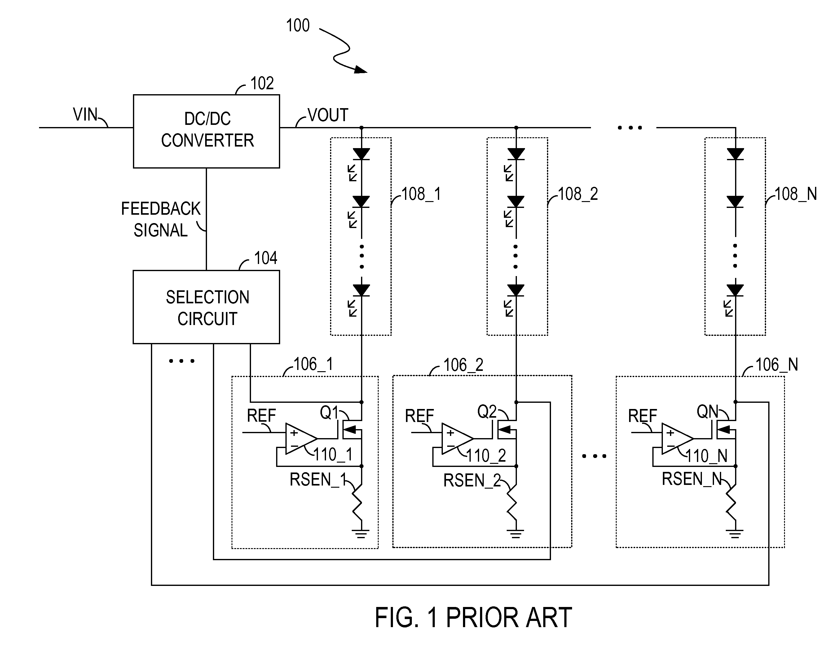
However, this solution may not be suitable for systems requiring relatively large LED current because of the larger amount of heat generated by the transistors Q1, Q2, .
As such, the power efficiency of the system may be decreased due to the power dissipation.
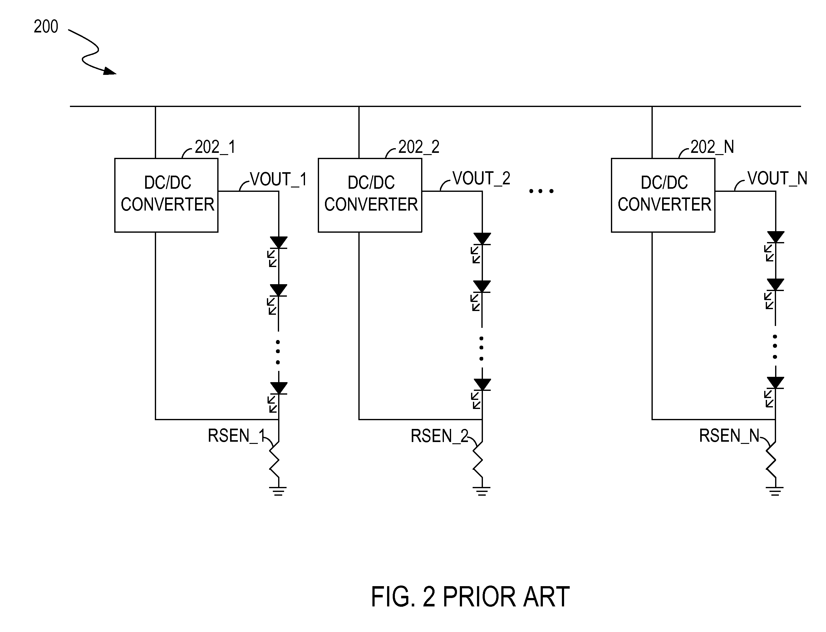
One of the drawbacks of this solution is that the system cost can be increased if there are a large number of LED strings, since a dedicated DC / DC converter is required for each LED string.

Method used


Image

  • Circuits and methods for powering light sources
  • Circuits and methods for powering light sources
  • Circuits and methods for powering light sources

Examples


Embodiment Construction

[0027]Reference will now be made in detail to the embodiments of the present invention. While the invention will be described in conjunction with these embodiments, it will be understood that they are not intended to limit the invention to these embodiments. On the contrary, the invention is intended to cover alternatives, modifications and equivalents, which may be included within the spirit and scope of the invention as defined by the appended claims.

[0028]Furthermore, in the following detailed description of the present invention, numerous specific details are set forth in order to provide a thorough understanding of the present invention. However, it will be recognized by one of ordinary skill in the art that the present invention may be practiced without these specific details. In other instances, well known methods, procedures, components, and circuits have not been described in detail as not to unnecessarily obscure aspects of the present invention. In the embodiments of the ...


PUM


Abstract

A driving circuit for powering a plurality of light-emitting diode (LED) light sources includes a power converter and a plurality of current balance controllers. The power converter receives an input voltage and provides a regulated voltage to the LED light sources. The current balance controllers coupled to the power converter control a plurality of currents through the LED light sources respectively. The current balance controllers receive a first reference signal indicative of a target average level and a second reference signal indicative of a maximum transient level, and regulate an average current of each of the currents to the target average level and a transient level of each of the currents within the maximum transient level.

Description

RELATED APPLICATION[0001]This application is a continuation-in-part of the co-pending U.S. application Ser. No. 12 / 221,648, entitled “Driving Circuit for Powering Light Sources”, filed on Aug. 5, 2008, which is hereby incorporated by reference in its entirety. This application also claims priority to U.S. Provisional Application No. 61 / 374,117, entitled “Circuits and Methods for Powering Light Sources”, filed on Aug. 16, 2010, which is hereby incorporated by reference in its entirety.BACKGROUND ART[0002]In a display system, one or more light sources are driven by a driving circuit for illuminating a display panel. For example, in a liquid crystal display (LCD) display system with light-emitting diode (LED) backlight, an LED array is used to illuminate an LCD panel. An LED array usually includes two or more LED strings, and each LED string includes a group of LEDs connected in series. For each LED string, the forward voltage required to achieve a desired light output may vary with LE...

Claims


Application Information

Patent Timeline
Patent Type & Authority Applications(United States)
IPC IPC(8): H05B37/02H05B41/16
CPCG09G3/3406H05B33/0848H05B33/0827H05B33/0815H05B45/14H05B45/46H05B45/375
Inventor LIU, DA
Owner O2 MICRO INT LTD
Learn More