Method and system for creating a vibration in an automobile

Inactive Publication Date: 2010-06-03
GM GLOBAL TECH OPERATIONS LLC
View PDF8 Cites 54 Cited by
  • Summary
  • Abstract
  • Description
  • Claims
  • Application Information

AI Technical Summary

Problems solved by technology

One of the changes involves the complexity of the electrical systems within automobiles, particularly alternative fuel vehicles, such as hybrid, battery electric, and fuel ce

Method used


Image

  • Method and system for creating a vibration in an automobile
  • Method and system for creating a vibration in an automobile
  • Method and system for creating a vibration in an automobile

Examples


Embodiment Construction

[0014]The following detailed description is merely exemplary in nature and is not intended to limit the invention or the application and uses of the invention. Furthermore, there is no intention to be bound by any expressed or implied theory presented in the preceding technical field, background, and brief summary, or the following detailed description.

[0015]The following description refers to elements or features being “connected” or “coupled” together. As used herein, “connected” may refer to one element / feature being mechanically joined to (or directly communicating with) another element / feature, and not necessarily directly. Likewise, “coupled” may refer to one element / feature being directly or indirectly joined to (or directly or indirectly communicating with) another element / feature, and not necessarily mechanically. However, it should be understood that although two elements may be described below, in one embodiment, as being “connected,” in alternative embodiments similar el...


PUM


Abstract

A method and system for operating an automotive electric motor having first and second components is provided. A desired frequency of vibration for the electric motor is selected. A current is caused to flow through at least one of the first and second components such that the second component moves relative to the first component. The current is modulated such that the motor vibrates at the desired frequency.

Description

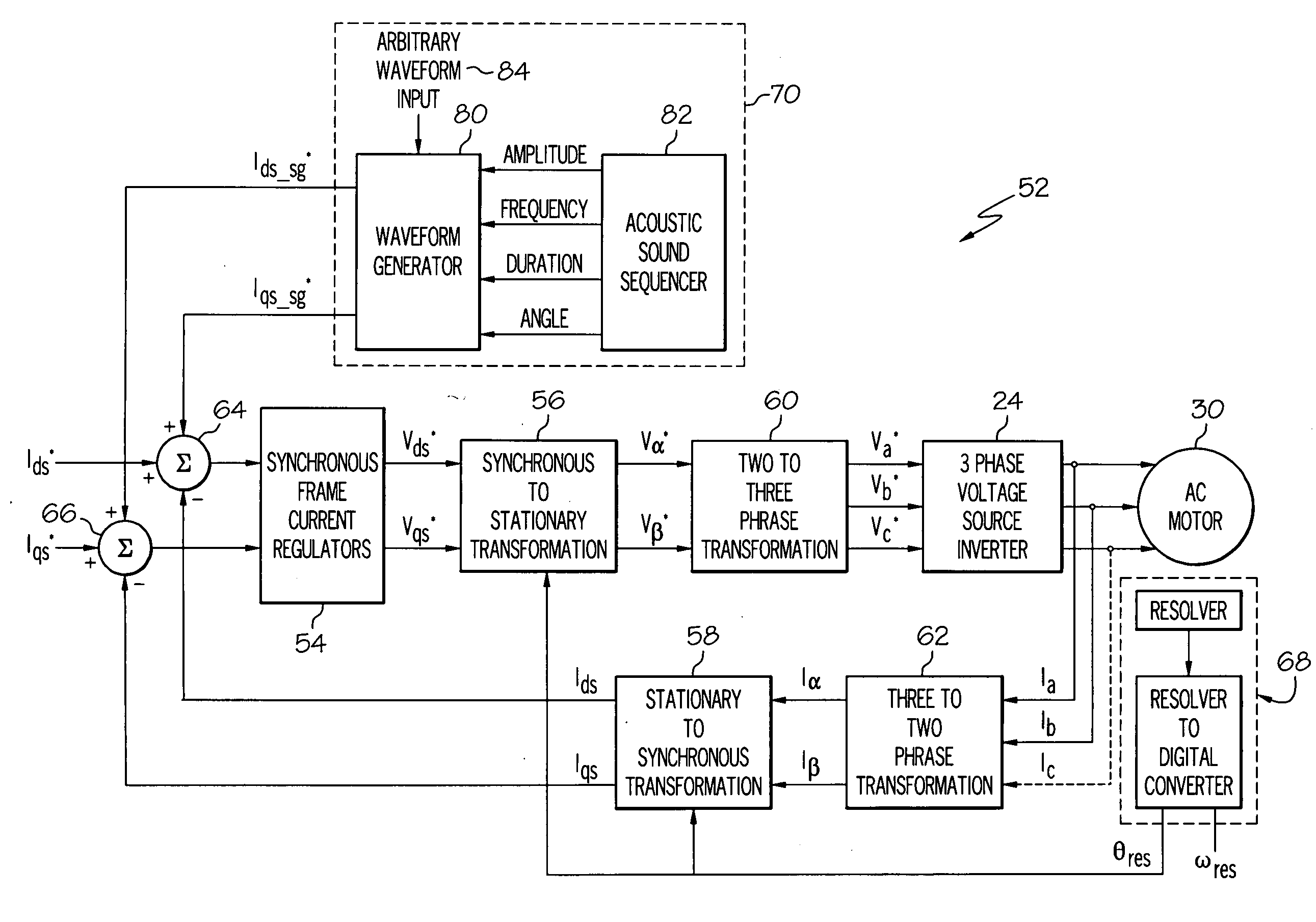
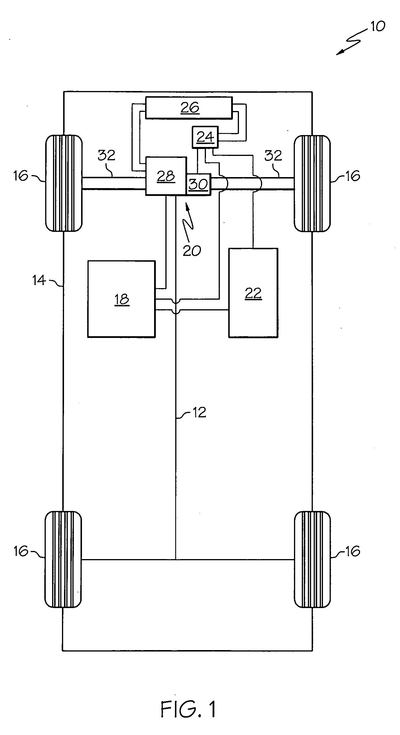
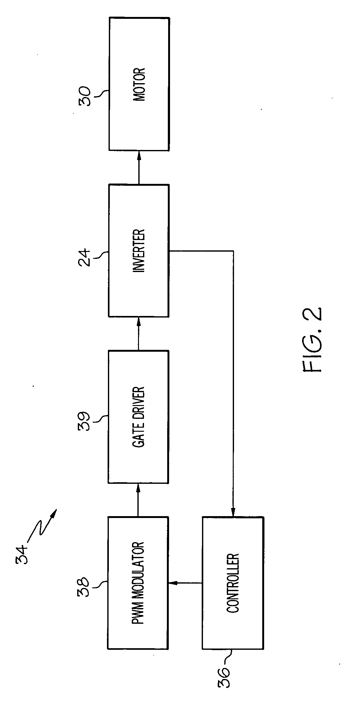
TECHNICAL FIELD[0001]The present invention generally relates to automobiles, and more particularly relates to a method and system for creating vibrations in automobiles.BACKGROUND OF THE INVENTION[0002]In recent years, advances in technology, as well as ever-evolving tastes in style, have led to substantial changes in the design of automobiles. One of the changes involves the complexity of the electrical systems within automobiles, particularly alternative fuel vehicles, such as hybrid, battery electric, and fuel cell vehicles. Such alternative fuel vehicles typically use one or more electric motors, perhaps in combination with another actuator, to drive the wheels.[0003]One of the advantages of driving the wheels with the electric motor is generally considered to be that the electric motors are relatively quiet, which provides for a comfortable driving experience. However, this also makes it difficult to hear the automobile to people outside the automobile, such as pedestrians, whi...

Claims


Application Information

Patent Timeline
IPC IPC(8): H02P6/10
CPCB60L11/14B60L15/025B60L2220/14B60L2270/145B60L2270/42Y02T10/70H02P6/10H02P21/06Y02T10/643Y02T10/7077Y02T10/7258B60Q5/008B60L50/16Y02T10/64Y02T10/72Y02T10/7072
Inventor NAGASHIMA, JAMES M.SCHULZ, STEVEN E.SON, YO CHANBEREISA, JONAS
Owner GM GLOBAL TECH OPERATIONS LLC
Why Eureka
Try Eureka