LED lighting fixture

a technology of led lighting fixtures and led lamps, which is applied in the direction of lighting and heating apparatus, semiconductor devices for light sources, instruments, etc., can solve the problems of shortening affecting reducing the service life of lighting fixtures, so as to achieve uniform lighting effect, increase the effect of effective illumination angle, and satisfactory reflection

Inactive Publication Date: 2010-06-03
KUN DIAN PHOTOELECTRIC ENTERPRISE
View PDF18 Cites 13 Cited by
  • Summary
  • Abstract
  • Description
  • Claims
  • Application Information

AI Technical Summary

Benefits of technology

[0010]The present invention has been accomplished under the circumstances in view. It is the main object of the present invention to provide a LED lighting fixture formed of a light guide board and a set of LEDs, which has a curved reflective layer provided at the light guide board to produce a satisfactory reflection effect, thereby effectively increasing the angle of illumination, providing a uniform lighting effect with enhanced brightness, and eliminating the multi-image and flashing problems of conventional daylight lamps.
[0011]To achieve this and other objects of the present invention, the LED lighting fixture comprises a cavity directly formed in a lamp holder, furniture, utensil, or the construction of a building, a light guide board, and a plurality of LEDs (light emitting diodes). The light guide board is made of a high transmissive material, comprising a clear base layer at the front side and a continuous piece of reflective layer at the back side. The reflective layer has a corrugated cross section. The LEDs are mounted within the cavity outside the light guide board, and adapted to emit light transversely into the inside of the light guide board for reflection by the reflective layer to increase the angle of illumination and to provide a uniform lighting effect having an enhanced brightness without causing multi-image and flashing.

Problems solved by technology

These conventional lighting fixtures have the common drawbacks of high consumption of electric energy and production of heat.
The production of heat greatly not only shortens the service life of the lighting fixture but also increases the ambient temperature.
Further, a daylight lamp causes a flashing problem that is harmful to the eyes.
However, LEDs may be too dim in bright light situations because of its unidirectional lighting feature.
Therefore, a LED lighting fixture has the drawback of limited angle of illumination.
However, this arrangement greatly complicates the fabrication of the lighting fixture and will also increase the cost.
Further, a lighting fixture constructed according to this arrangement may produce multiple images, not practical to substitute for conventional daylight lamps.
However, the design of the arched convex portion of the reflective layer still has a limitation in reflection.

Method used


Image

  • LED lighting fixture
  • LED lighting fixture
  • LED lighting fixture

Examples


first embodiment

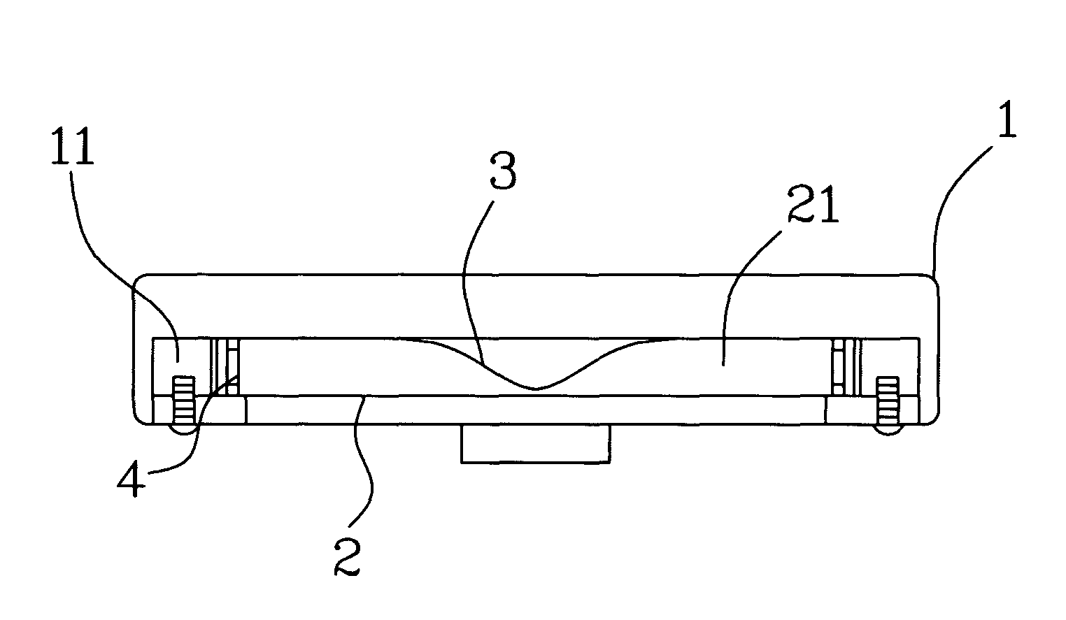
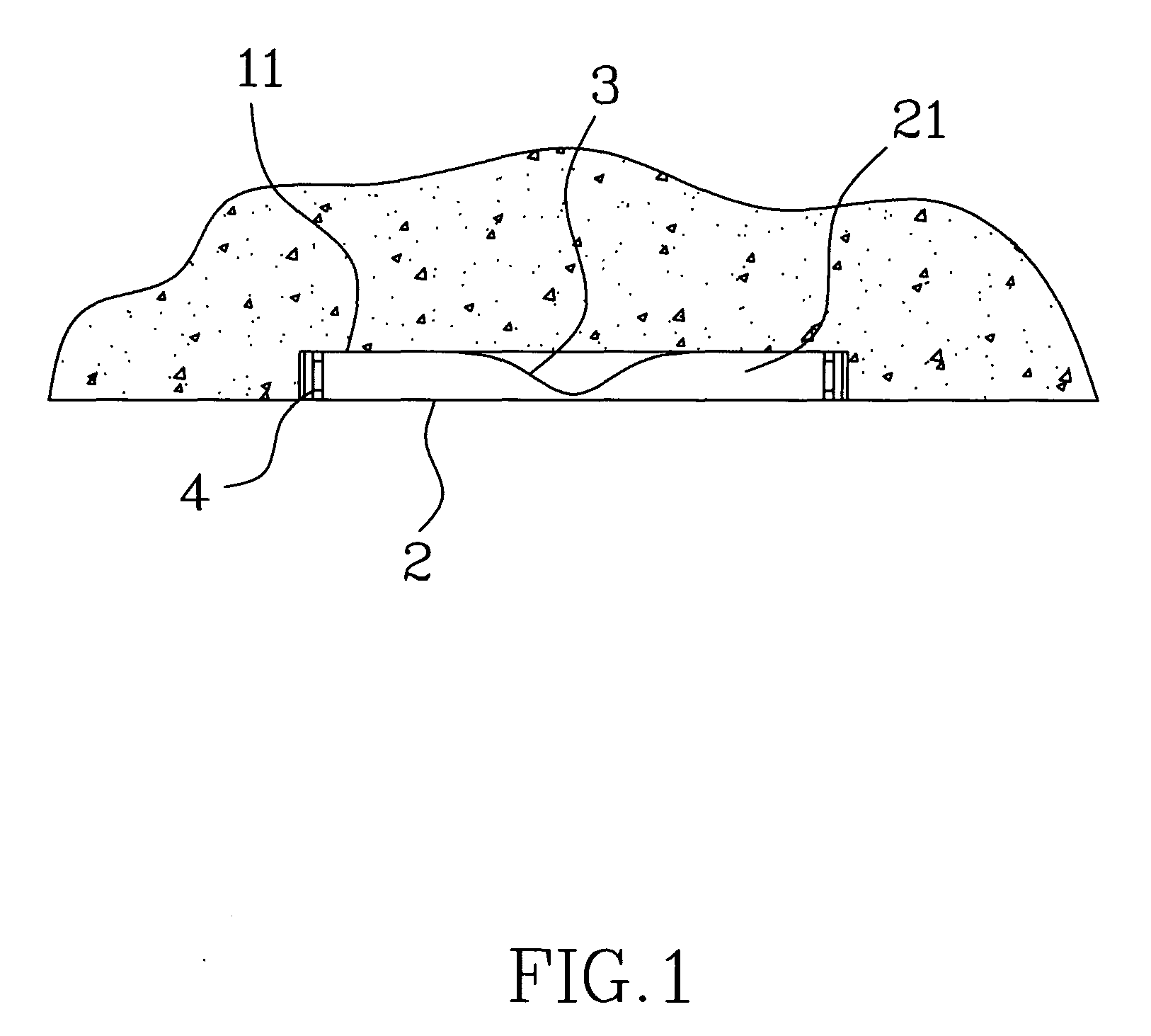
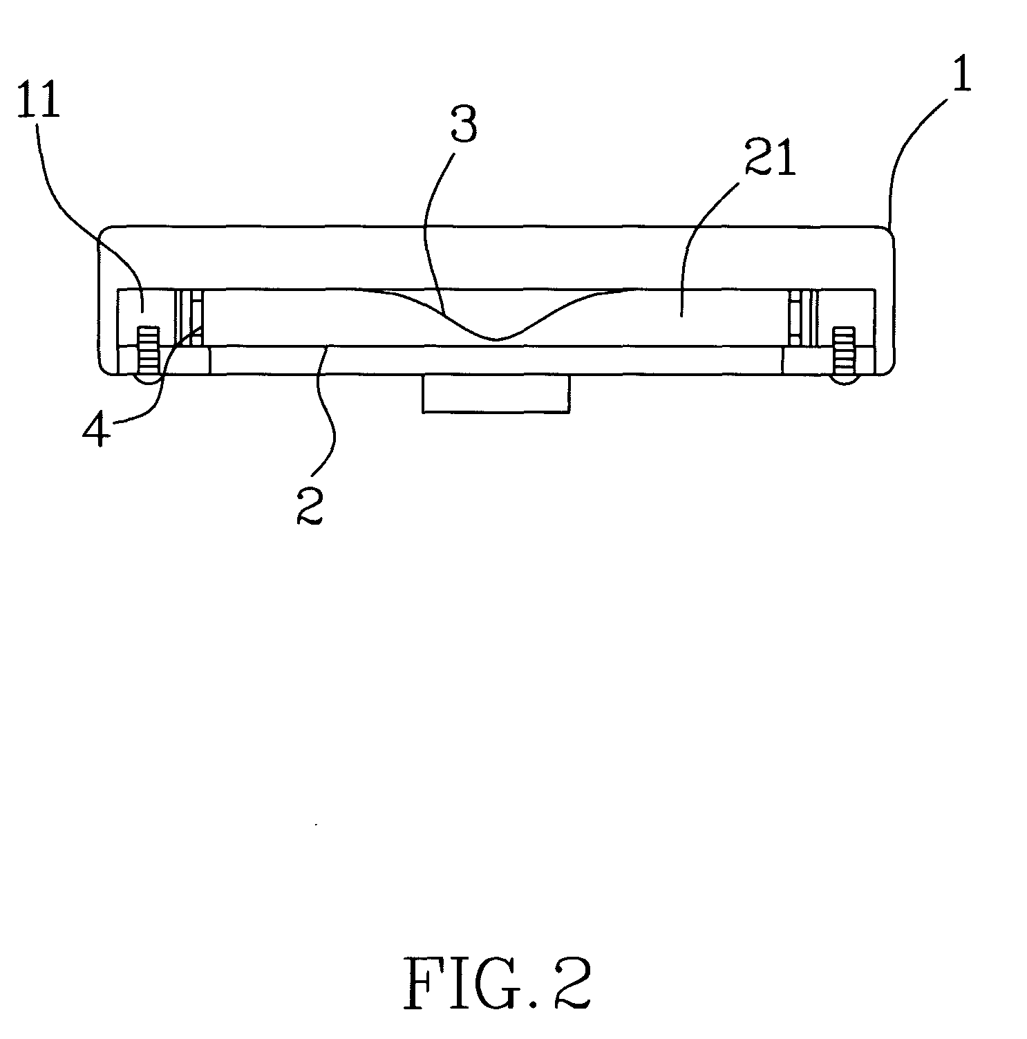
[0023]Referring to FIGS. 1˜5, a LED lighting fixture in accordance with the present invention is shown comprising a cavity 11, a light guide board 2, and a plurality of LEDs (light emitting diodes) 4.

[0024]The cavity 11 may be directly formed in a lamp holder 1, a piece of furniture, a utensil, or the construction of a building.

[0025]The light guide board 2 is made of a high transmissive material and mounted inside the cavity 11, having a clear base layer 21 at its front side a continuous piece of reflective layer 3 at its back side. The cross section of the reflective layer 3 shows a corrugated pattern. Further, the reflective layer 3 has two straight end edges 31, two arched shoulder portions 32 respectively extended from the two straight end edges 31 on the middle and respectively terminating in a V-shaped tip 33.

[0026]The LEDs 4 are mounted within the cavity 11 outside the light guide board 2, and adapted to emit light transversely into the inside of the light guide board 2 from...

second embodiment

[0029]Referring to FIGS. 6˜10, a LED lighting fixture in accordance with the present invention is shown comprising a cavity 11, a light guide board 2, and a plurality of LEDs (light emitting diodes) 4.

[0030]The cavity 11 may be directly formed in a lamp holder 1, a piece of furniture, a utensil, or the construction of a building.

[0031]The light guide board 2 is made of a high transmissive material and mounted inside the cavity 11, having a clear base layer 21 at its front side a continuous piece of reflective layer 3 at its back side. The clear base layer 21 of the light guide board 2 has a light input surface 22 disposed at one lateral side, and a light output surface 23 disposed at the front side and abutted against the light output surface 23 at an angle. The reflective layer 3 has a corrugated cross section, and an inner side bonded to the whole surface area of said clear base layer 21 beyond the light input surface 22 and the light output surface 23. The inner side of the refle...


PUM


Abstract

A LED lighting fixture includes a light guide board, which is made of a high transmissive material and directly mounted in the cavity of a lamp holder, furniture, utensil, or the construction of a building, having a clear base layer at the front side and a continuous piece of reflective layer with a corrugated cross section at the back side, and a plurality of LEDs mounted within the cavity outside the light guide board and controlled to emit light transversely into the inside of the light guide boards for reflection by the reflective layer to increase the angle of illumination and to provide a uniform lighting effect having an enhanced brightness without multi-image and flashing.

Description

BACKGROUND OF THE INVENTION[0001]1. Field of the Invention[0002]The present invention relates to lighting fixtures and more specifically, to a LED lighting fixture, which uses a light guide board having a corrugated cross section and covered with a reflective layer to guide light from LEDs so as to increase the angle of illumination and to provide a uniform lighting effect having an enhanced brightness without multi-image and flashing.[0003]2. Description of the Related Art[0004]The history of lamp extends for long. Since the invention of lamp to produce light, it greatly improves the living style of people. Nowadays, a variety of lighting fixtures of different outer appearances have been disclosed for different purposes. Because of heavy market demand, improvements on function as well as on application should never stop.[0005]Despite of different design changes, conventional lighting fixtures use a lamp bulb or lamp tube to produce light. These conventional lighting fixtures have t...

Claims


Application Information

Patent Timeline
Patent Type & Authority Applications(United States)
IPC IPC(8): F21V1/00
CPCF21V7/0016F21V13/04F21V33/0012G02B6/0046F21Y2101/02F21Y2105/00G02B6/0021F21V33/006F21Y2115/10
Inventor LEE, CHENG SHENG
Owner KUN DIAN PHOTOELECTRIC ENTERPRISE
Why Eureka
Try Eureka