

Drill sleeve for a dental drill
- Summary
- Abstract
- Description
- Claims
- Application Information
AI Technical Summary
Benefits of technology
Problems solved by technology
Method used
Image

Examples
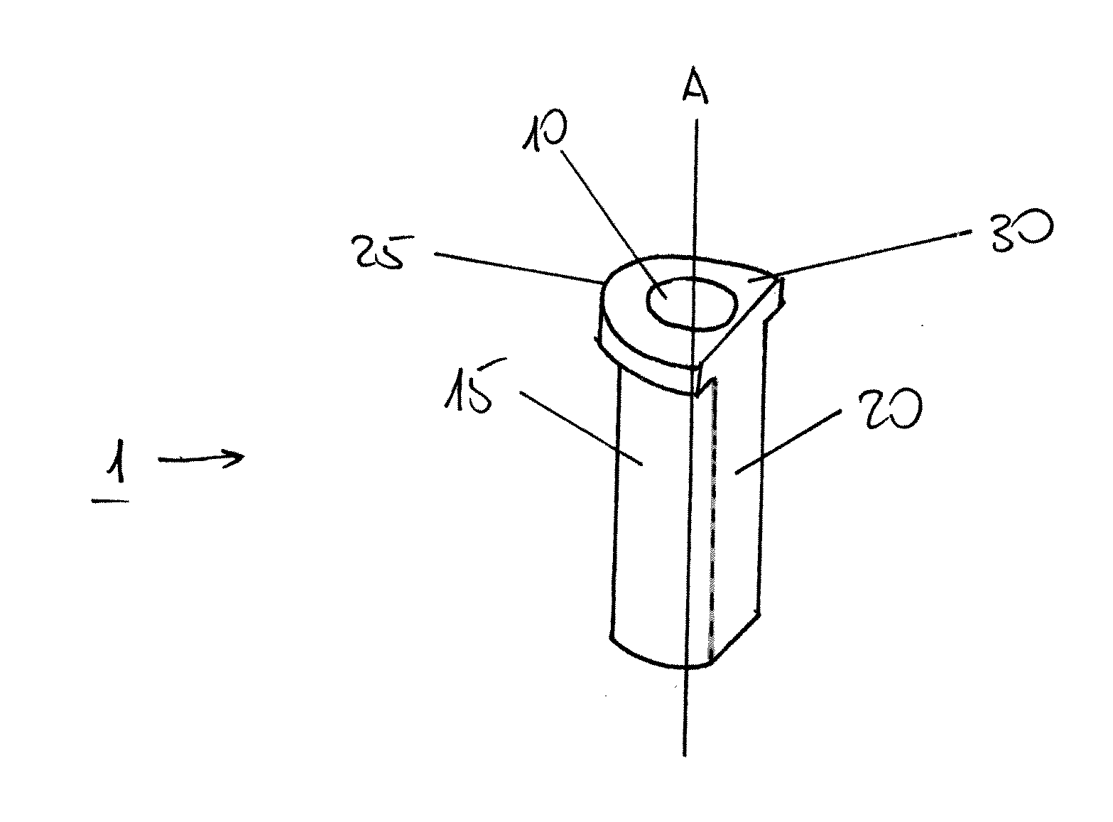
second embodiment
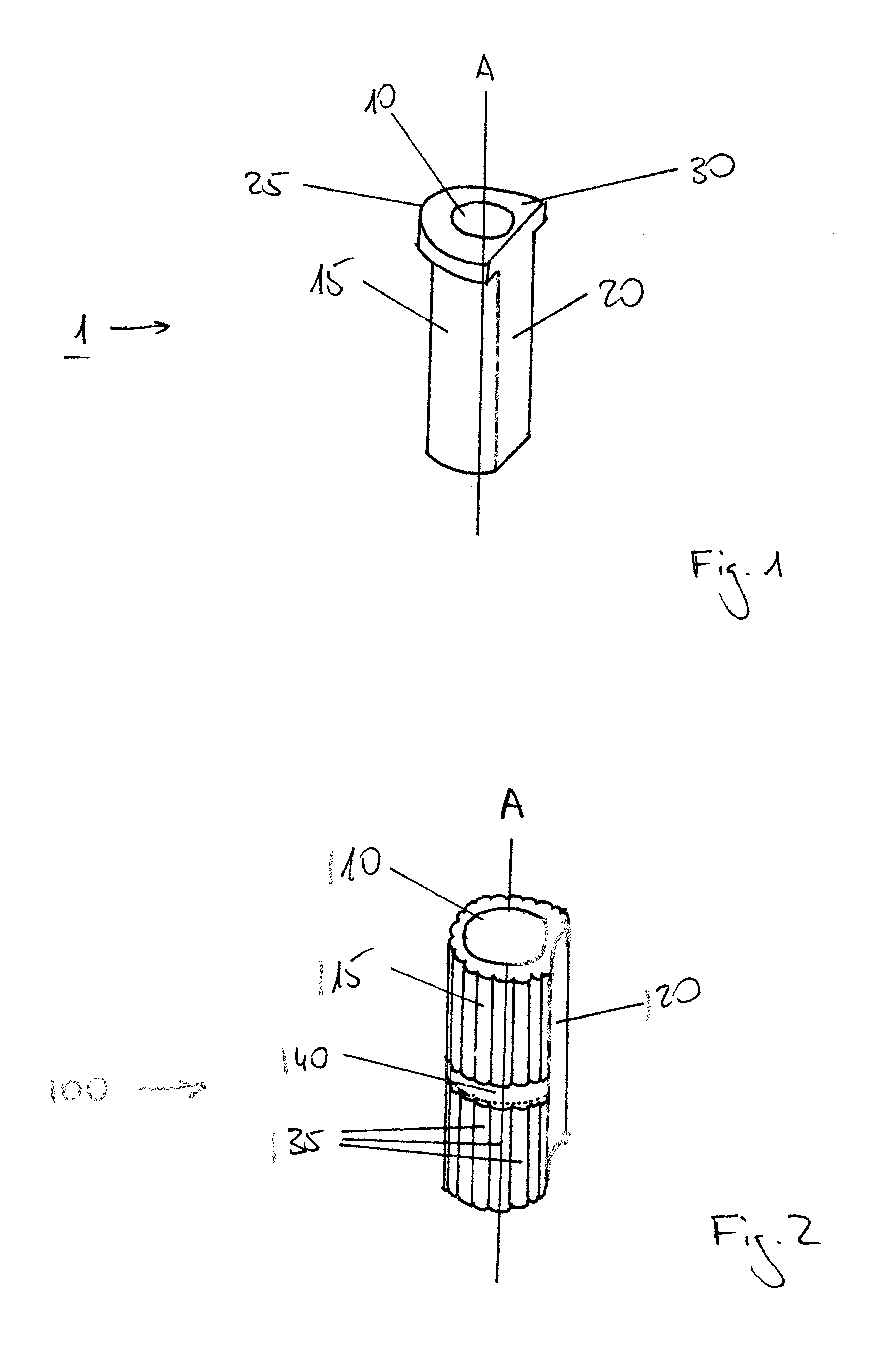
[0031]the drill sleeve 100 shown in FIG. 2 also has a longitudinal axis A, a circular inner surface 110, and an outer surface 115 with a longitudinal concave area 120. In addition to the concave area 120, the outer surface 115 also has several longitudinal projections 135, which are interrupted by an essentially circular groove 140.
third embodiment
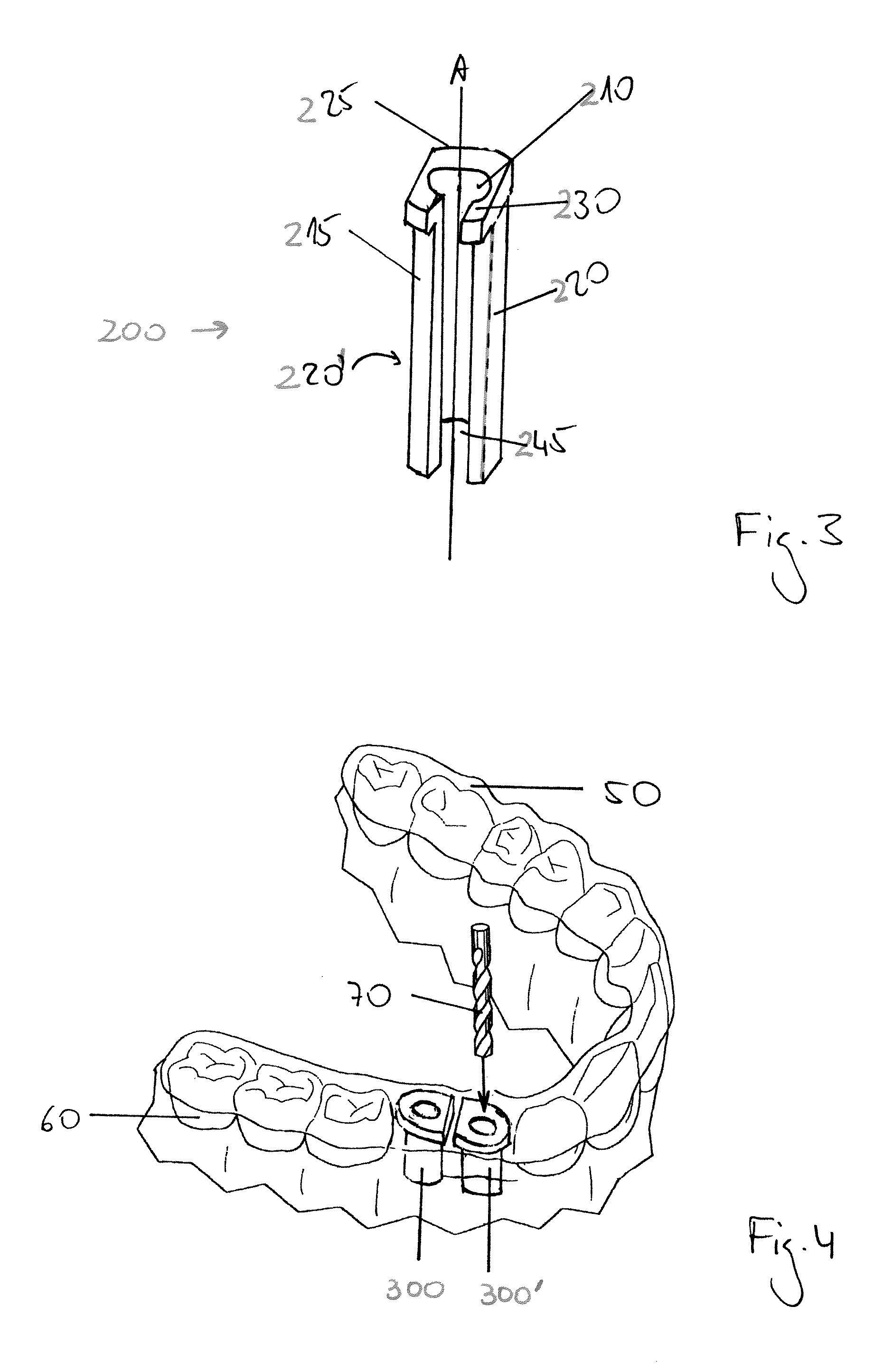
[0032]In a third embodiment shown in FIG. 3, the outer surface 215 of the drill sleeve 200 comprises two longitudinal flattened areas 220, 220′, and, at its coronal end 225, a circumferential flange 230. This embodiment of the drill sleeve 200 is further characterized by a longitudinal slit 245.
[0033]FIG. 4 is a schematic representation of a template 50, which is placed on a patient's dentition 60. The template 50 includes two drill sleeves 300, 300′ according to any of prior embodiments of the present invention, which are inserted into the template 50 at the implantation position. In order to prepare a drill hole in the patient's jaw-bone, the dental surgeon will insert a drill 70 through the drill sleeves 300, 300′, using the drill sleeves 300, 300′ as guidance for the drill 70.
PUM
 Abstract
Description
Claims
Application Information