
Automatic Flow Tracking System and Method

a flow tracking and automatic technology, applied in the field of doppler flow measurement of blood flow, can solve the problems of inability to continue real-time monitoring of cardiac health in its present form, over- or under-estimate the actual flow contained in the system, and achieve the effect of not increasing the sensitivity to nois

Inactive Publication Date: 2010-06-03
USCOM LTD
View PDF6 Cites 11 Cited by
  • Summary
  • Abstract
  • Description
  • Claims
  • Application Information

AI Technical Summary

Benefits of technology

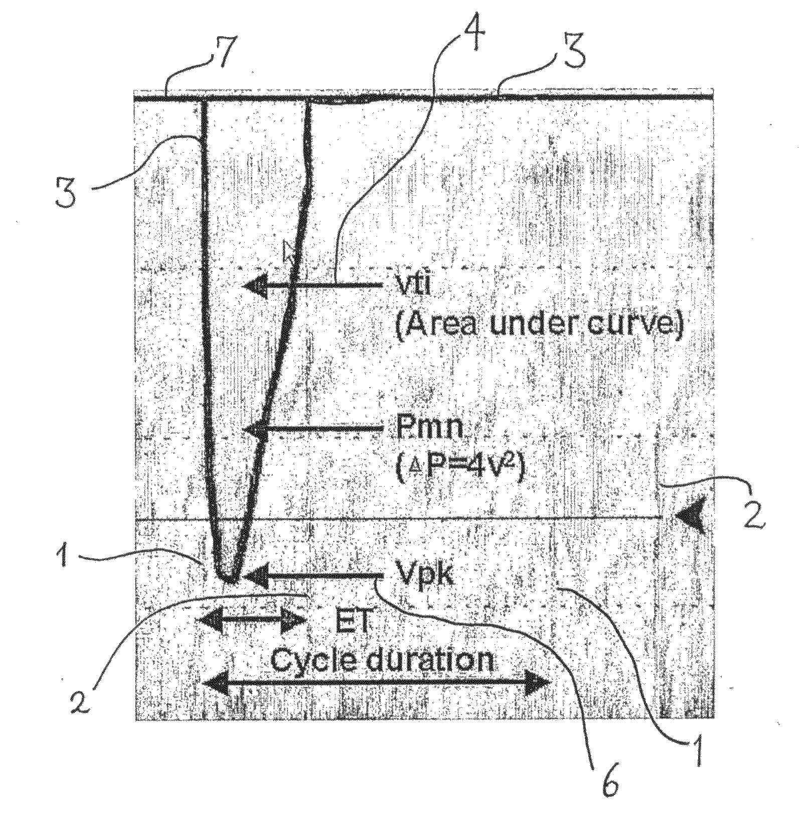
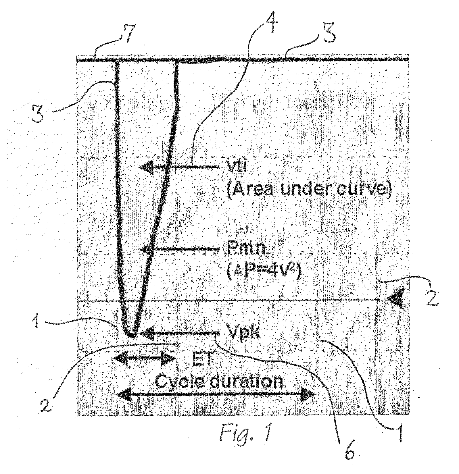
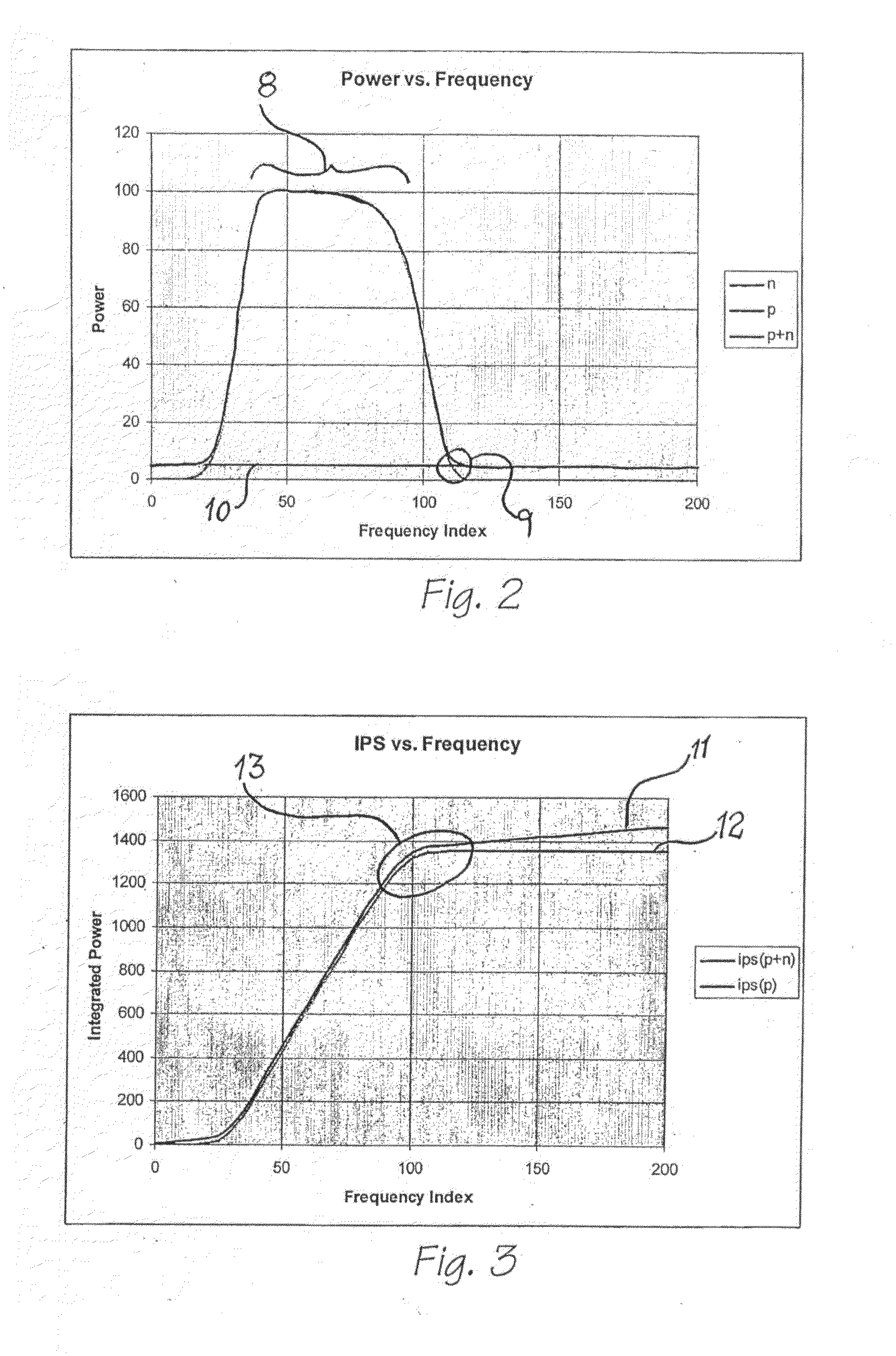
"The present invention provides a method and device for automatically tracking the flow of fluid in a heart, particularly a Doppler signal, and extracting relevant cardiac monitoring parameters. This can be useful for real-time monitoring of cardiac function in patients. The method involves extracting a flow envelope from the monitoring signal, removing extraneous flows, and extracting features from the flow envelope and monitoring signal. The maximum flow rate can be derived from the maximum frequency signal level. The device includes a means of detecting a Doppler spectral signal, processing it to automatically extract cardiac parameters, and displaying a visual representation of the processed signal. The invention has the advantage of providing a more accurate and reliable method for cardiac monitoring."

Problems solved by technology

However, the extraction of relevant cardiac measures from the irregular profile of the Doppler flow spectrogram still relies on the manual outlining of the flow regions which is time-consuming and labour intensive.
As such, this method is not suitable in its present form for continual real-time monitoring of the cardiac health of a patient.
Automatic trace algorithms of Doppler spectrograms are known; however, they consistently either over- or under-estimate the actual flow contained in the system.
This is mainly due to flows and artefacts inherent in the heart, particularly at the instants of valve opening and closing, and the presence of noise in the recorded signal.
Thus, the results are of limited use.

Method used


Image

  • Automatic Flow Tracking System and Method
  • Automatic Flow Tracking System and Method
  • Automatic Flow Tracking System and Method

Examples


Embodiment Construction

[0047]The preferred embodiment is designed to operate with a suitably modified cardiac monitoring systems such as those disclosed in U.S. Pat. No. 6,565,513 entitled “Ultrasonic Cardiac Output Monitor”, the contents of which are hereby incorporated by reference in their entirety. FIG. 27 illustrates the operation of a system utilised in accordance with the aforementioned patent application. The cardiac output of the heart of a patient 210 is monitored utilising an ultrasonic transducer 211 attached to a processing device 212 which processes the return signal from the transducer to provide an output trace 220, illustrated in FIG. 28.

[0048]The processing device 212 can be structured as illustrated schematically in FIG. 29 with the transducer 211 interconnected to a Digital Signal Processing device 232. The DSP device is further interconnected to a microprocessor 233, memory 234 and I / O device controller 235 by means of bus 236. It will be obvious to those skilled in the art that other...


PUM


Abstract

A method of determining the blood flow characteristics from a monitoring signal indicative of blood flow in the vicinity of a heart, the method including the steps of: (a) extracting a flow envelope from the monitoring signal; (b) extracting a series of temporal markers from the flow envelope. (c) removing extraneous flows such as valve opening and closing flows from the flow envelope; (d) extracting features from the flow envelope and monitoring signal, such as peak velocity; (e) Producing cardiac parameters based on said monitoring signal.

Description

RELATED APPLICATIONS[0001]This application claims priority to PCT Application No._PCT / AU2006 / 000338 filed Mar. 15, 2006, and Australian Application No. 2005901253 filed Mar. 15, 2005, the disclosures of which are hereby incorporated by reference in their entireties.FIELD OF THE INVENTION[0002]The present invention relates to the field of Doppler flow measurements of blood flow and, in particular, to the automatic tracking of the envelope of a Doppler flow spectral profile for extracting relevant cardiac parameters in real-time. The method can also be applied to non-real time analysis.BACKGROUND OF THE INVENTION[0003]Image recognition and processing techniques are increasingly becoming important in many aspects of clinical diagnosis and monitoring. In cardiography, non-invasive methods such as Doppler flow echocardiography are gaining preference over invasive techniques, particularly for seriously ill patients. However, the extraction of relevant cardiac measures from the irregular p...

Claims


Application Information

Patent Timeline
Patent Type & Authority Applications(United States)
IPC IPC(8): A61B8/06A61B5/026G06K9/00
CPCA61B5/026A61B5/7257A61B8/06A61B8/065G01S15/8979A61B8/42A61B8/467G01S7/52036A61B8/08A61B8/488
Inventor STRAND, ROBERT
Owner USCOM LTD
Learn More