Door coupling system

Active Publication Date: 2010-06-10
HAIER US APPLIANCE SOLUTIONS INC
View PDF18 Cites 22 Cited by
  • Summary
  • Abstract
  • Description
  • Claims
  • Application Information

AI Technical Summary

Benefits of technology

[0005]As described herein, the exemplary embodiments overcome o

Problems solved by technology

Generally these gear or chain transmissions introduce backlash in the operation of the doors so that the door operation is often unsatisfactory in term

Method used


Image

  • Door coupling system
  • Door coupling system
  • Door coupling system

Examples


Embodiment Construction

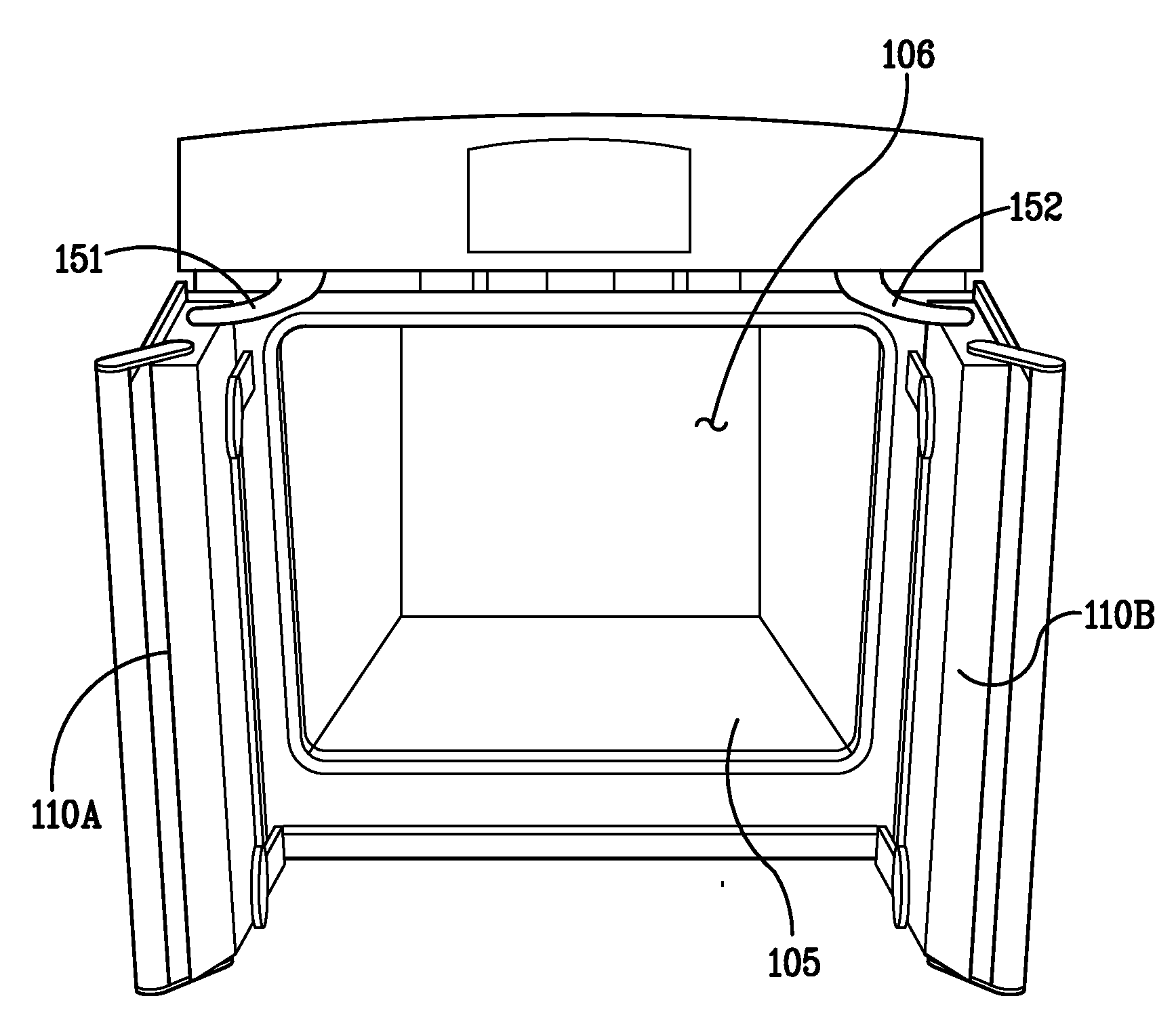
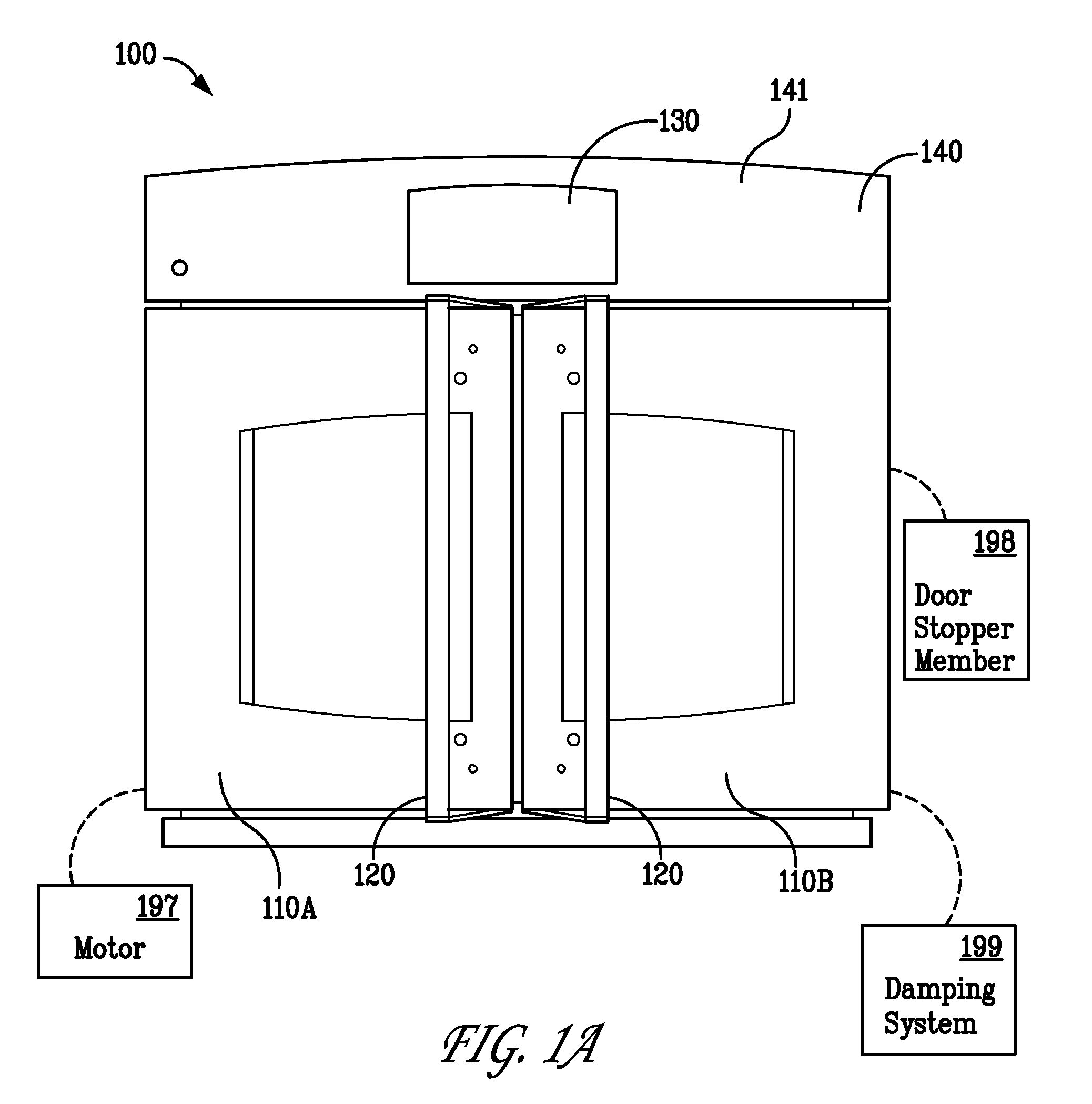
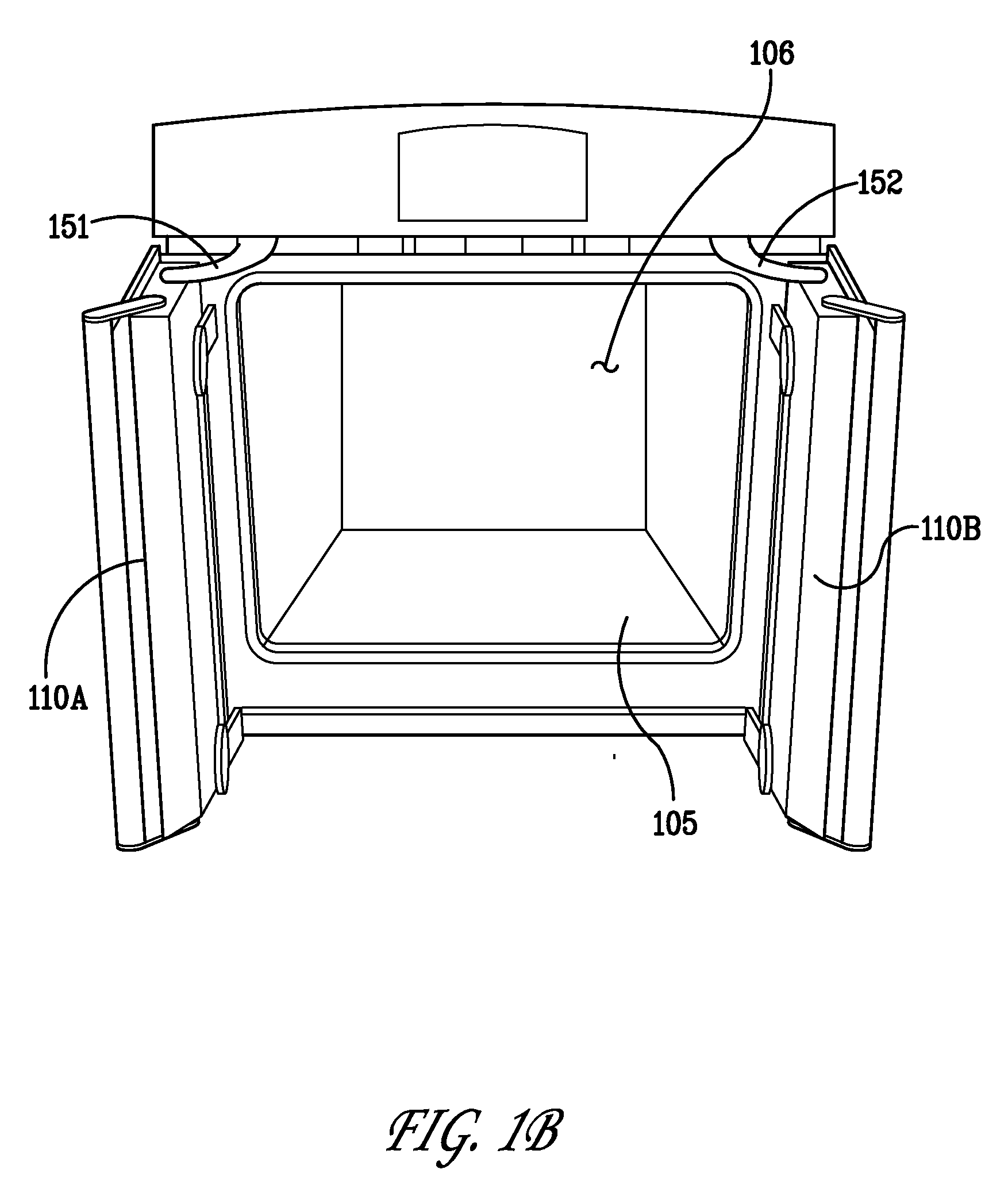
[0020]FIGS. 1A and 1B illustrate an exemplary appliance 100 incorporating a door coupling system in accordance with an exemplary embodiment of the invention. By way of a non-limiting example, the appliance 100 is shown as a freestanding cooking oven. The invention can be used in other types of appliances, such as refrigerators, ovens, clothes washers, dryers, and dishwashers. As can be seen in FIGS. 1A and 1B, the appliance 100 includes French doors (e.g. first and second doors 110A, 110B).

[0021]The disclosed exemplary embodiments provide for a door coupling mechanism that allows for the simultaneous operation of both the first and second doors 110A, 110B when an opening or closing force is applied to either one of the doors. The exemplary configurations of the door coupling mechanism couples the first and second doors 110A, 110B through at least one ternary link that is pivotally mounted on a structural member or frame of the appliance 100. The exemplary embodiments also provide fo...


PUM


Abstract

An apparatus including a frame forming an internal cavity, the frame having an opening for accessing the internal cavity, a first door and a second door mounted to the frame and a door coupling mechanism for effecting a substantially simultaneous movement of the first door and second door relative to the frame, the door coupling mechanism including a first door link, a second door link and at least one ternary link, the first door link being rotatably coupled to the first door and the at least one ternary link, the second door being rotatably coupled to the second door and the at least one ternary link.

Description

BACKGROUND OF THE INVENTION[0001]The exemplary embodiments of the present invention generally relate to door coupling systems. More particularly, the exemplary embodiments relate to coupling systems for French style doors and apparatus incorporating such coupling systems.[0002]Generally French style door design provides several benefits over conventional appliance doors such doors for cooking ranges and refrigerators. One benefit of French doors is enhanced ergonomics of accessing contents to be placed in or removed from an internal cavity of the appliance. French doors also minimize the space needed to swing the doors open and closed due to the reduced width of the door when compared to a single door appliance having a similar face width.[0003]Generally French door systems without interconnected doors are operated with two hands where both doors are generally opened simultaneously. Some French door systems also require that the doors be opened in a specific order (e.g., the left si...

Claims


Application Information

Patent Timeline
IPC IPC(8): E05F17/00
CPCE05F17/004E05Y2201/416F24C15/02A21B3/02E05Y2900/30
Inventor PATIL, MAHENDRA MADHUKARSHAFFER, TIMOTHY SCOTTWATKINS, DEREK LEE
Owner HAIER US APPLIANCE SOLUTIONS INC
Why Eureka
Try Eureka