Cleaning appliance comprising a microwave drying system

Inactive Publication Date: 2010-06-10
MEIKO MASCHENBAU
View PDF31 Cites 9 Cited by
  • Summary
  • Abstract
  • Description
  • Claims
  • Application Information

AI Technical Summary

Benefits of technology

[0012]It is therefore an object of the present invention to provide a cleaning appliance which at least substantially avoids the above-described drawbacks of known cleaning ap

Problems solved by technology

More extensive problems arise in commode rinsers in which clinging germs (viruses or bacteria) can harbor an increased risk of infection.
However, the drying of the object to be cleaned, in particular thermal drying, is a major challenge in terms of desig

Method used


Image

  • Cleaning appliance comprising a microwave drying system
  • Cleaning appliance comprising a microwave drying system
  • Cleaning appliance comprising a microwave drying system

Examples


Example

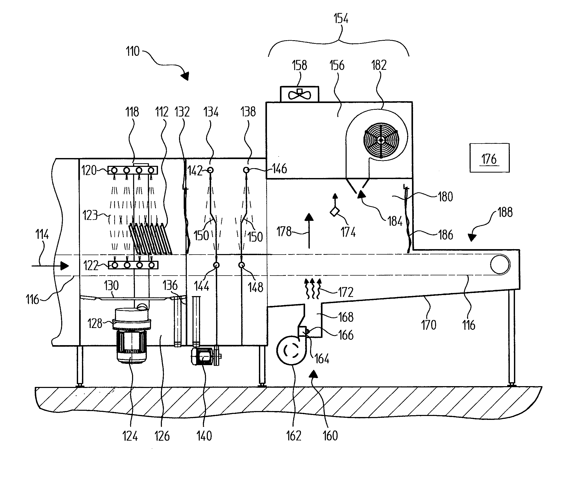
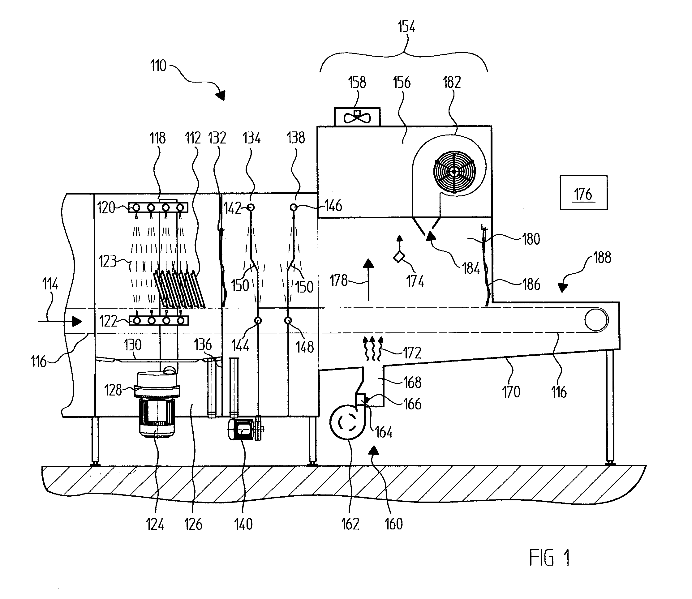
[0046]FIG. 1 is a schematic sectional side view of a first exemplary embodiment of a cleaning appliance. In this case, the cleaning appliance is configured as a continuous-flow dishwashing machine 110. In this continuous-flow dishwashing machine 110, objects 112 to be cleaned are transported in a direction of continuous flow 114 or direction of transportation through treatment zones or cleaning zones of the continuous-flow dishwashing machine 110. A conveying device 116, which is embodied in the illustration according to FIG. 1 as an endless transportation belt, transports the object 112 to be cleaned through the various cleaning zones of the continuous-flow dishwashing machine 110.

[0047]Viewed in the direction of transportation 114 of the object 112 to be cleaned, the object to be cleaned passes first through a rinsing zone 118. A first rinsing system 120 and also a second rinsing system 122 are located within the rinsing zone 118. Cleaning fluid 123 issues from the rinsing system ...


PUM


Abstract

A cleaning appliance is provided for cleaning objects to be cleaned. The cleaning appliance comprises at least one cleaning zone for cleaning the object to be cleaned using a cleaning liquid. The cleaning appliance further comprising a microwave drying device which can be used for at least partially drying the object to be cleaned.

Description

[0001]This nonprovisional application is a continuation of International Application No. PCT / EP2008 / 002263, which was filed on Mar. 20, 2008, and which claims priority to German Patent Application No. DE 10 2007 025 262.7, which was filed in Germany on May 30, 2007, and which are both herein incorporated by reference.BACKGROUND OF THE INVENTION[0002]1. Field of the Invention[0003]The invention relates to a cleaning appliance for cleaning objects to be cleaned in a cleaning zone. Cleaning appliances of this type are used for example in the form of continuous-flow dishwashing machines or single-chamber dishwashing machines in rinsing technology or in the form of commode rinsers for cleaning objects to be cleaned having comparatively high liquid waste in the field of nursing homes, elderly care homes or hospitals.[0004]2. Description of the Background Art[0005]A large number of different variations of cleaning appliances for cleaning objects to be cleaned or objects to be rinsed are kn...

Claims


Application Information

Patent Timeline
IPC IPC(8): B08B3/00
CPCA47L15/0013A47L15/0015A47L15/0076A47L15/241A47L15/4223A47L15/485A47L2601/04A47L2601/12A47L15/4234
Inventor GAUS, BRUNONAEGER, THOMASPEUKERT, THOMASSCHERINGER, STEFANWIEGAND, INGO
Owner MEIKO MASCHENBAU
Why Eureka
Try Eureka