Devices and methods for displaying decorative ornaments

a technology for mounting devices and ornaments, applied in the direction of light support devices, electron beam welding apparatus, arc welding apparatus, etc., can solve the problems of limited capability and desirability and special limitations of conventional ornament connectors

Inactive Publication Date: 2010-06-10
SWAROVSKI LIGHTING LTD
View PDF2 Cites 6 Cited by
  • Summary
  • Abstract
  • Description
  • Claims
  • Application Information

AI Technical Summary

Benefits of technology

[0021]Another aspect of the invention is a decorative ornament arrangement including: at least one mounting means adapted to mount the arrangement to a support structure; at least two substantially parallel spines mounted to the at least one mounting means; a plurality of pairs of mounting posts projecting from the parallel spines; and a plurality of perforated ornaments mounted to the plurality of pairs of mounting posts; wherein the mounting means, spines, and mounting posts are fabricated from one plate. In one aspect, the arrangement may be laser cut from thin plate.
[0022]A still further aspect of the invention is an connector adapted to couple two or more ornament chains having posts or pins, the connector including at least one cross bar; a plurality of uprights extending from the at least one cross bar; and at least one perforation in each of the plurality of uprights, the at least one perforation adapted to engage the post of the ornament chain. In one aspect of the invention, the connector may assume the form of the letter H, and may be referred to as an “H connector.” In one aspect of the invention the connector may be fabricated from plate, for example, from thin plate, for example, by means of laser jet cutting. Another aspect of the invention is a method of fabricating the connector described above, for example, using the procedures of the methods described to fabricate other structures disclosed herein, for instance, the methods of fabricating the device for displaying decorative ornaments discussed above.

Problems solved by technology

Though conventional connectors and means for connecting ornaments are very effective when mounting ornaments, conventional connectors can have limitations when providing longer strings of ornaments or connecting larger ornaments, for example, for large chandeliers.
The limitations of conventional ornament connectors are particularly acute as the number and size of ornaments being connected increases, for example, as the size of a chandelier increases.
Ever increasing customer demands for larger and more elaborate chandeliers tax the capability and desirability of conventional ornament connectors.
For instance, as the diameter of the chandelier increases, the length of a “chain” or “run” of ornaments mounted on the chandelier increases and the tendency for the ornaments to twist or become misaligned increases.
Such long runs of ornaments are prone to unsightly twisting when conventional connecting methods and connectors are used.
The realignment of such twisted chains is typically time consuming and, often, ineffective in providing the proper orientation of the ornaments desired.
Also, as the size of chandeliers increase, the size of the ornaments typically used also increases.
For example, small ornaments simply are not aesthetically appealing when mounted on large chandeliers.
Typically, as the size of the ornaments increases, the weight of the ornament also increases.
The increased weight of larger ornaments, for example, larger glass crystal ornaments, can exceed the load capacity of conventionally connected ornament chains.

Method used


Image

  • Devices and methods for displaying decorative ornaments
  • Devices and methods for displaying decorative ornaments
  • Devices and methods for displaying decorative ornaments

Examples


Embodiment Construction

[0092]The details and scope of the aspects of the present invention can best be understood upon review of the attached figures and their following descriptions.

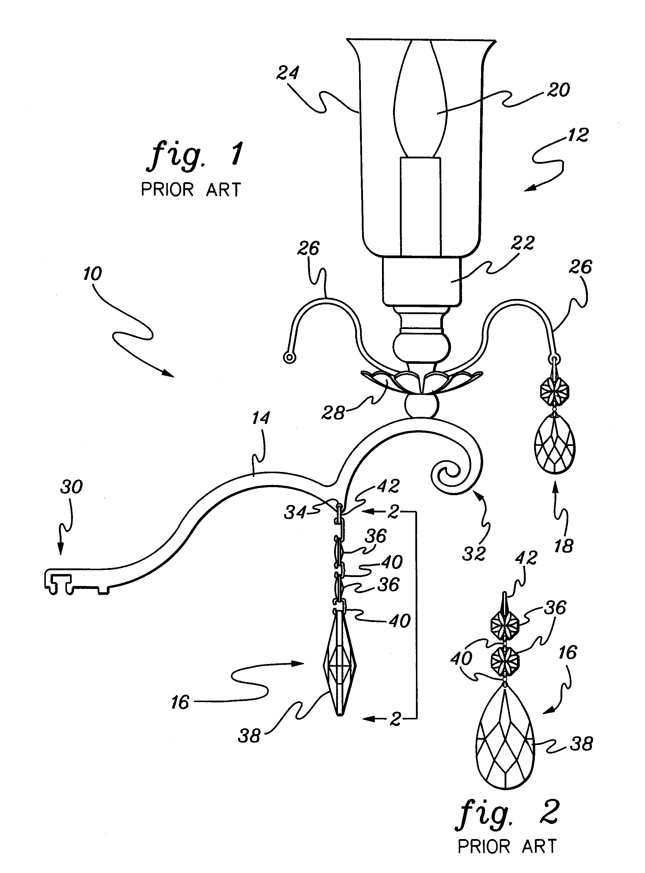
[0093]FIG. 1 is a side elevation view of a fixture mounting assembly 10 having decorative ornaments mounted and connected according to the prior art. Assembly 10 includes a fixture 12, a fixture mounting arm 14, and one or more decorative ornament assemblies 16 and 18. In this typical prior art assembly, fixture 12 is a light fixture having a light bulb 20 mounted in a fixture base 22 and a light shade 24, which in this example is a hurricane light shade, mounted to fixture base 22. Assembly 10 also includes a pair of ornament mounting arms 26 to which ornament assembly 18 is hung and a bobeche 28. Fixture mounting arm 14 includes a first end 30 adapted for mounting to a support, a free second end 32 to which fixture 12 mounted, and an ornament mounting hole 34 to which ornament assembly 16 is mounted.

[0094]FIG. 2 is a front ...


PUM

PropertyMeasurementUnit
thicknessaaaaaaaaaa
thicknessaaaaaaaaaa
lengthaaaaaaaaaa

Abstract

Arrangements and methods for connecting and mounting decorative ornaments, for example, beads, crystals, or gems, are disclosed. The arrangements and methods are particularly useful in mounting ornaments in decorative fixtures, such as chandeliers. In one aspect, an arrangement is provided that includes a first ornament having two mounting apertures and a second ornament having at least one mounting aperture; and at least one connector for connecting the first ornament to the second ornament whereby when hung the two apertures of the first ornament are laterally disposed from each other. Multiple pre-formed connectors are disclosed for use in connecting ornaments, such as ornament chains. Mounting hooks, mounting devices, and mounting arrangements are also provided for attaching ornaments to a support, for instance, mounting devices fabricated from thin plate, for example, by laser cutting. Aspects of the invention may be used for large fixtures, such as large chandeliers, to minimize or prevent the twisting of long chains of ornaments and to support the loading of larger ornaments.

Description

CROSS REFERENCE TO RELATED APPLICATIONS[0001]This application is a continuation-in-part application of and claims priority from pending U.S. application Ser. No. 10 / 774,264 filed on Feb. 5, 2004 [Attorney Ref. 2350.422], the disclosure of which is incorporated by reference herein in its entirety.[0002]This application is related to the following applications, which are commonly assigned as the above application:[0003]Utility patent application entitled “ARRANGEMENTS, BRACES, AND METHODS FOR SUPPORTING AN ARM OF AN ORNAMENTAL FIXTURE” filed on Feb. 5, 2004 and having Ser. No. 10 / 773,551 [Attorney Ref. 2350.421].[0004]Utility patent application entitled “METHODS FOR DISPLAYING DECORATIVE ORNAMENTS” filed on Feb. ______, 2005 and having serial number ______ [Attorney Ref. 2350.422B].[0005]These applications are incorporated by reference herein in their entirety.FIELD OF THE INVENTION[0006]This invention relates, generally, to arrangements for and methods for mounting decorative ornamen...

Claims


Application Information

Patent Timeline
Patent Type & Authority Applications(United States)
IPC IPC(8): F16M13/02B26D3/00B23B35/00B23H1/00B23K15/00B23K9/00B23K26/00F21V5/06
CPCF21V5/06F21S8/061Y10T409/303752Y10T408/03F21V17/164Y10T83/0591Y10T83/06Y10T83/929
Inventor BAYER, GEORGSCHONBEK, ANDREW J.TAVANO, CARLJARVIS, ROBINTUCKER, DANIELPATNODE, TIMOTHY
Owner SWAROVSKI LIGHTING LTD
Why Eureka
Try Eureka