Vehicle lower body structure

a lower body and vehicle technology, applied in the field of vehicle lower body, can solve the problems of achieve the effect of increasing the strength of the frame that forms the vehicle compartment and increasing the weight of the vehicle body

Inactive Publication Date: 2010-06-10
TOYOTA JIDOSHA KK
View PDF1 Cites 14 Cited by
  • Summary
  • Abstract
  • Description
  • Claims
  • Application Information

AI Technical Summary

Benefits of technology

[0007]The invention provides a vehicle lower body structure with which the strength of a frame that forms a vehicle compartment is increased without an increase in the weight of a vehicle body.

Problems solved by technology

However, upsizing of the cross members (14A, 16) or an increase in the thickness of the cross members (14A, 16) results in an increase in the weight of the vehicle body.

Method used


Image

  • Vehicle lower body structure
  • Vehicle lower body structure
  • Vehicle lower body structure

Examples


first embodiment

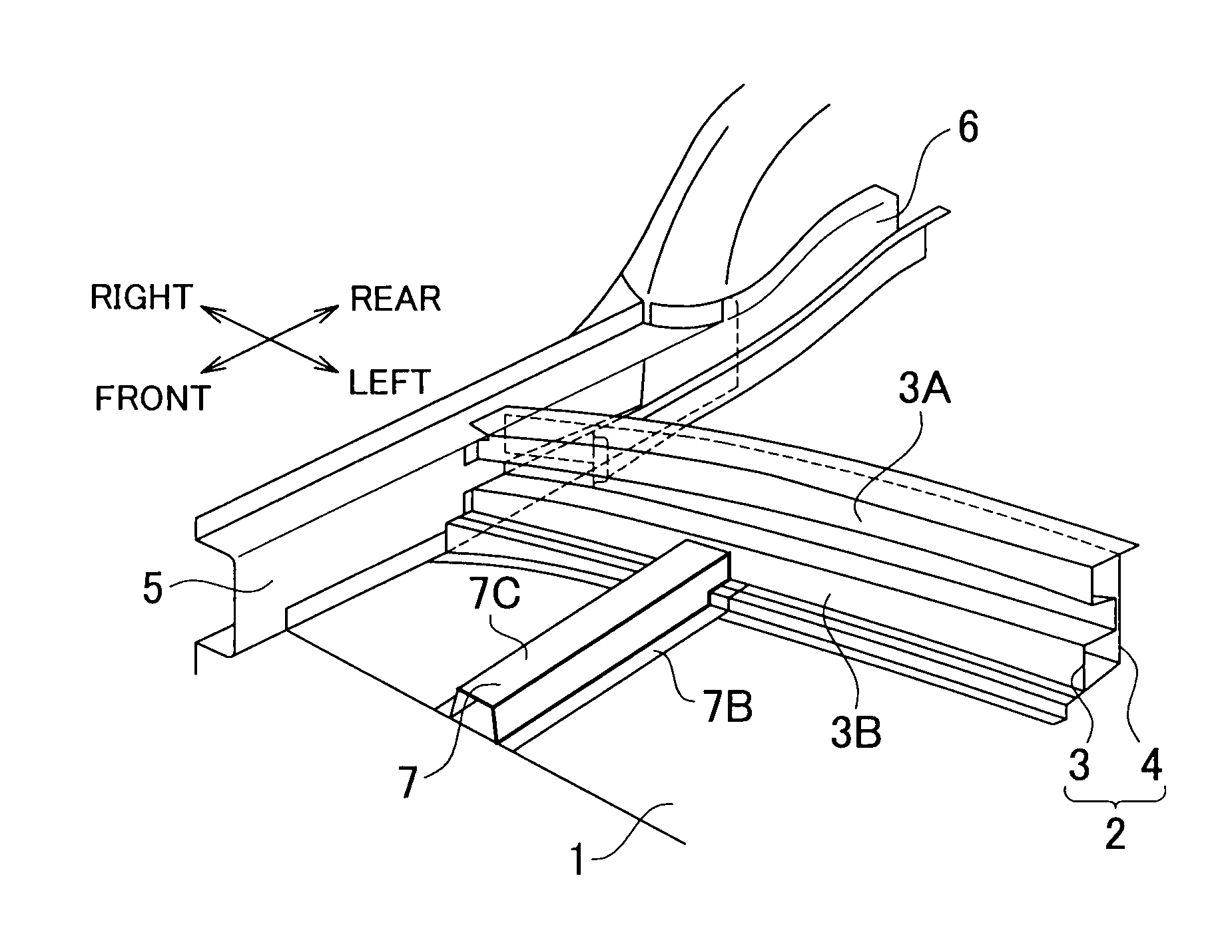
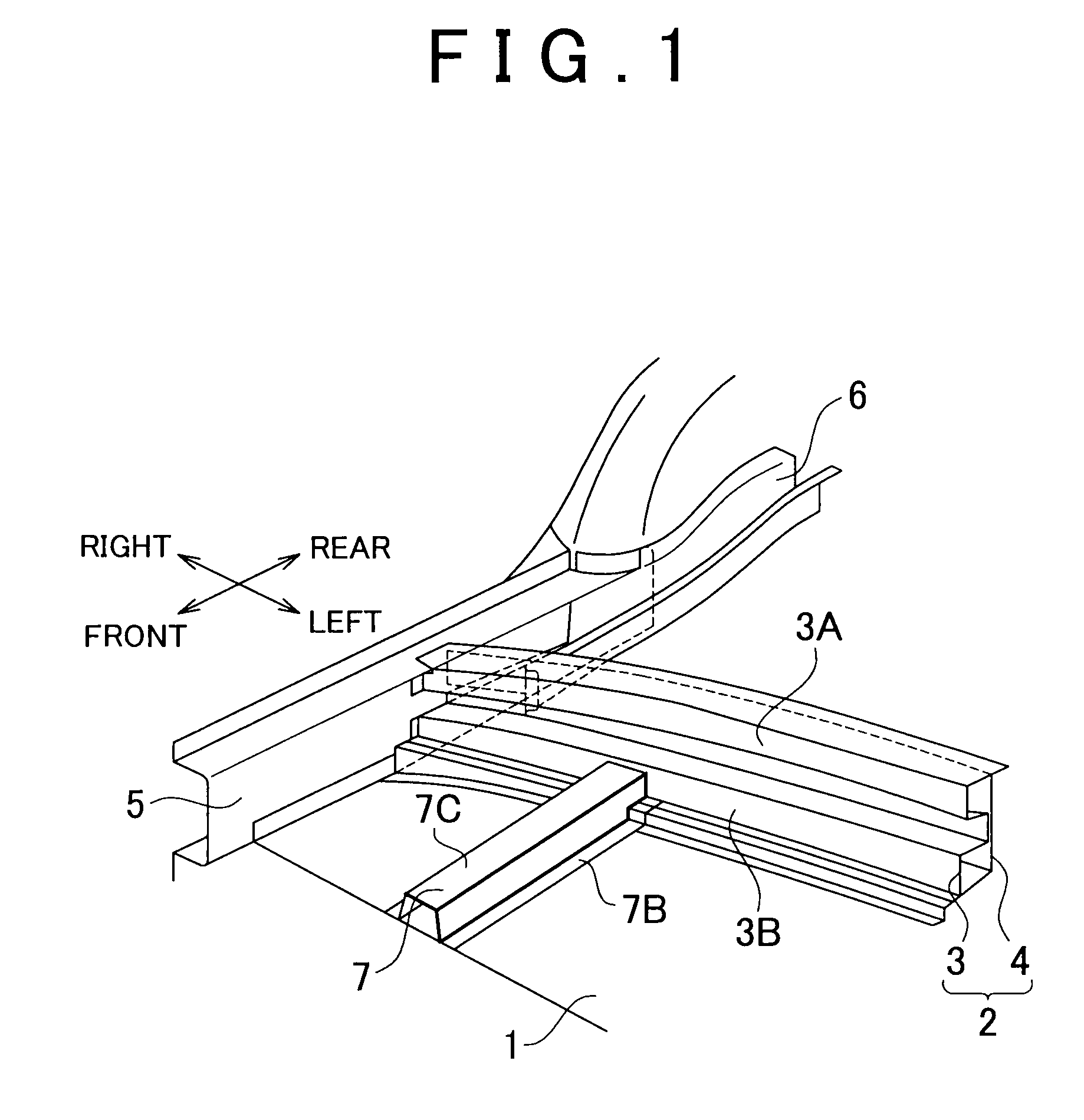
[0025]The vehicle lower body structure according to the invention is, for example, a structure of a lower portion of a vehicle compartment of an automobile. As shown in FIG. 1, at a rear portion of a front floor (floor panel) 1 that forms a lower portion of the vehicle compartment, a center floor cross member 2 is arranged as a cross member that forms a step portion which extends upward from the front floor 1. The center floor cross member 2 is formed of a front cross member 3 that is a first cross member which defines part of the vehicle compartment and which faces the front of a vehicle body, and a rear cross member 4 that is a second cross member which is connected to the rear face of the front cross member 3.

[0026]A right portion and a left portion (left portion is not shown) of the front floor 1 are connected to rocker inner members 5 each of which has a hat-shaped cross section, and rear floor side members 6 are connected to rear portions of the rocker inner members 5. Paired ...

second embodiment

[0044]FIG. 5 is a vertical cross-sectional view showing a cross member of a vehicle lower body structure according to the invention.

[0045]The second embodiment differs from the first embodiment in that a flat front cross member 13 is used instead of the front cross member 3 that has the corrugated cross section, and a rear cross member 14 that has a corrugated cross section is used instead of the flat rear cross member 4.

[0046]The rear cross member 14 is formed in such a manner that projection face portions 14A and 14B that form the corrugations project toward the rear of the vehicle body. The rear cross member 14 forms a plurality of closed section portions in cooperation with the front cross member 13.

[0047]More specifically, a vertical wall portion 13A that forms a flat portion of the front cross member 13 is connected to the front face of a recessed face portion 14C that is formed between an upper projection face portion 14A and a lower projection face portion 14B of the rear cr...

third embodiment

[0051]FIG. 6 is a vertical cross-sectional view showing a cross member of a vehicle lower body structure according to the invention.

[0052]The third embodiment differs from the second embodiment in that a rear cross member 24 is used instead of the rear cross member 14. The front floor 1 in the second embodiment has an extended portion that extends rearward. The rear cross member 24 is formed by bending the extended portion of the front floor 1 in such a manner that the projection face portions 14A and 14B are formed as in the second embodiment. The third embodiment differs from the second embodiment in that the rear cross member 24 is formed integrally with the front floor 1.

[0053]Therefore, instead of the front cross member 13 that is connected at the lower connection portion 13E to the front floor 1, a front cross member 23 is used. A lower portion of the vertical wall portion 13A of the front cross member 23 is connected to a lower portion (portion that is lower than the lower pr...


PUM


Abstract

A vehicle lower body structure includes a cross member that extends in the vehicle-width direction, that defines part of a vehicle compartment, and that includes a first cross member which is formed of a plate member and a second cross member which is formed of a plate member and which is provided at a position closer to the rear of a vehicle than the first cross member, the first cross member and the second cross member facing each other. A plurality of closed section portions is formed by the first cross member and the second cross member. The closed section portions are connected to each other via a portion at which the first cross member and the second cross member are continuously overlapped with each other.

Description

INCORPORATION BY REFERENCE[0001]The disclosure of Japanese Patent Application No. 2008-312151 filed on Dec. 8, 2008 and Japanese Patent Application No. 2009-264083 filed on Nov. 19, 2009 each including the specification, drawings and abstract are incorporated herein by reference in their entireties.BACKGROUND OF THE INVENTION[0002]1. Field of the Invention[0003]The invention relates to a vehicle body structure of, for example, an automobile, and more specifically to a vehicle lower body structure that includes a cross member which extends in the vehicle-width direction.[0004]2. Description of the Related Art[0005]There is a vehicle lower body structure of an automobile in which a step portion, a so-called raised portion (kick-up portion), is formed on a floor of a vehicle compartment. Japanese Patent Application Publication No. 2006-290140 (JP-A-2006-290140) (refer especially to abstract and FIG. 3) describes a vehicle lower body structure of this type. According to JP-A-2006-290140...

Claims


Application Information

Patent Timeline
Patent Type & Authority Applications(United States)
IPC IPC(8): B62D25/20
CPCB62D25/025B62D25/2036B62D25/2027B62D25/20
Inventor MORI, TAKEO
Owner TOYOTA JIDOSHA KK
Why Eureka
Try Eureka