AI technical title is built by Patsnap AI team. It summarizes the technical point description of the patent document.
a technology of energy transfer and wires, applied in the direction of electric energy management, driver interaction, inductance, etc., can solve the problems of inconvenient electrical energy transfer, inconvenient use, and inefficient power transfer
Active Publication Date: 2010-06-10
WITRICITY CORP
View PDF100 Cites 518 Cited by
Summary
Abstract
Description
Claims
Application Information
AI Technical Summary
This helps you quickly interpret patents by identifying the three key elements:
Problems solved by technology
Method used
Benefits of technology
Benefits of technology
The patent describes a new wirelessenergy transfer technique that allows for efficient transfer of power between resonators over mid-range distances, using high-Q resonators with low intrinsic-loss rates. This technique can be applied to a wide range of electronic devices and can provide power levels from picowatts to kilowatts. The resonators are designed to have a high degree of coupling, allowing for efficient energy transfer even at off-center frequencies. The patent also discusses the use of sub-wavelength resonators with near-fields that extend significantly longer than the characteristic sizes of the resonators. Overall, this technology provides a more efficient and flexible way to transfer power wirelessly over large distances.
Problems solved by technology
However, this type of radiative transfer is very inefficient because only a tiny portion of the supplied or radiated power, namely, that portion in the direction of, and overlapping with, the receiver is picked up.
Such inefficient power transfer may be acceptable for data transmission, but is not practical for transferring useful amounts of electrical energy for the purpose of doing work, such as for powering or charging electrical devices.
However, these directed radiation schemes may require an uninterruptible line-of-sight and potentially complicated tracking and steering mechanisms in the case of mobile transmitters and / or receivers.
In addition, such schemes may pose hazards to objects or people that cross or intersect the beam when modest to high amounts of power are being transmitted.
Method used
Image
Click on the blue label to locate the original text in one second.
Reading with bidirectional positioning of images and text.
[0362]We disclose examples of high-Q resonators for wirelesspower transmission systems that may wirelessly power or charge devices at mid-range distances. High-Q resonator wirelesspower transmission systems also may wirelessly power or charge devices with magnetic resonators that are different in size, shape, composition, arrangement, and the like, from any source resonators in the system.
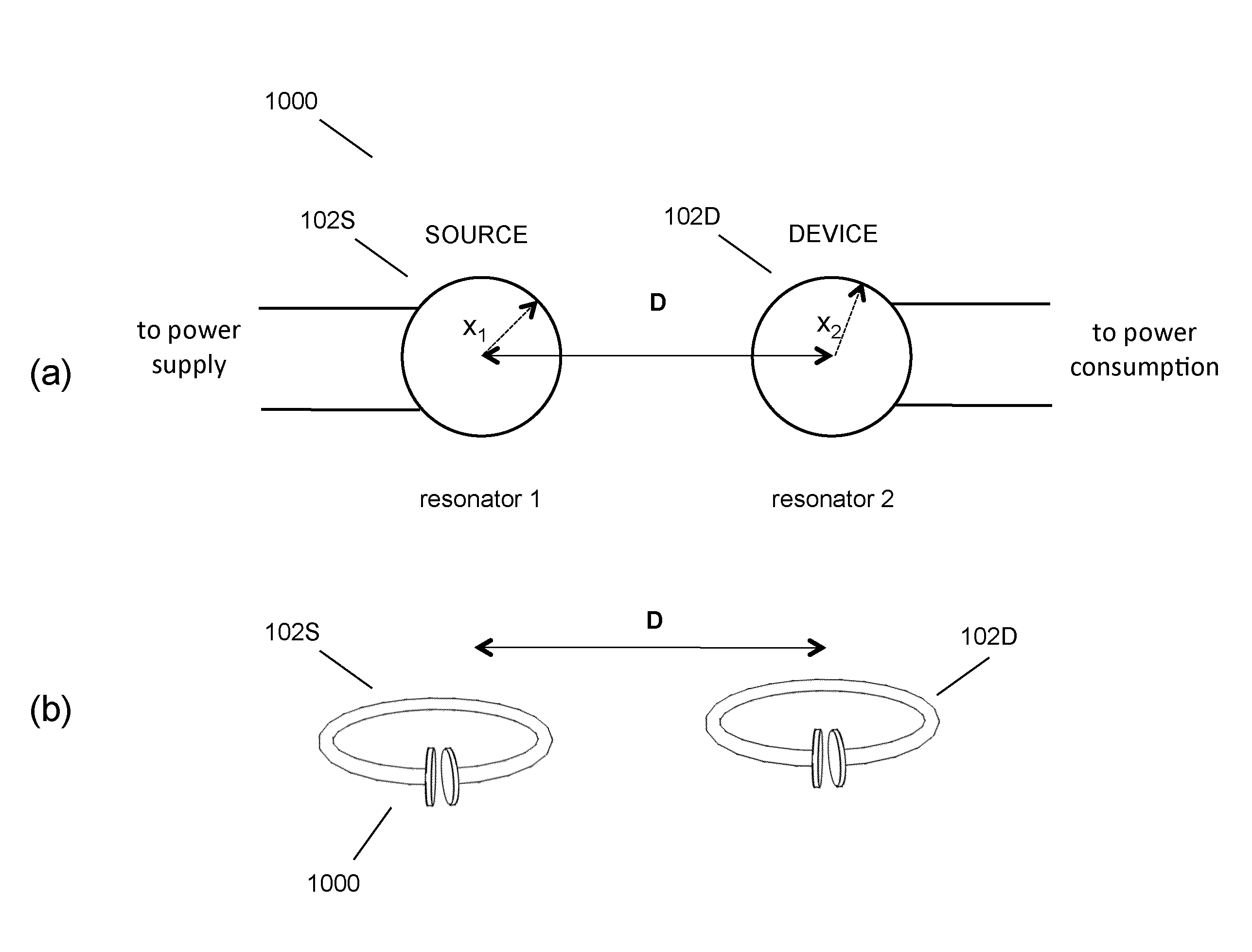
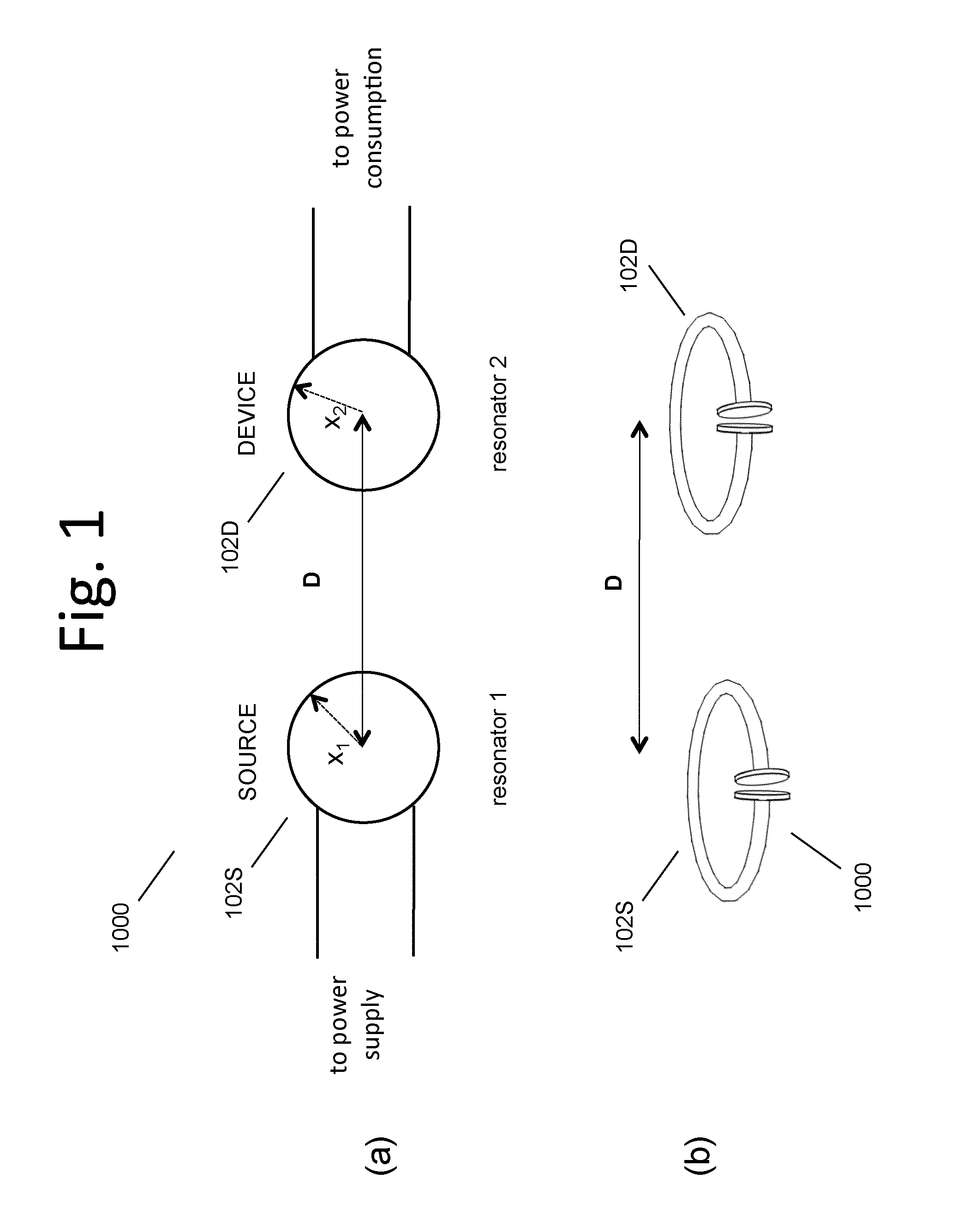
[0363]FIGS. 1(a)(b) shows high level diagrams of two exemplary two-resonator systems. These exemplary systems each have a single source resonator 102S or 104S and a single device resonator 102D or 104D. FIG. 38 shows a high level block diagram of a system with a few more features highlighted. The wirelessly powered or charged device 2310 may include or consist of a device resonator 102D, device power and control circuitry 2304, and the like, along with the device 2308 or devices, to which either DC or AC or both AC and DC power is transferred. The energy or power source...
PUM
Abstract
Described herein are improved capabilities for a source resonator having a Q-factor Q1>100 and a characteristic size x1 coupled to an energy source, and a second resonator having a Q-factor Q2>100 and a characteristic size x2 coupled to an energy drain located a distance D from the source resonator, where the source resonator and the second resonator are coupled to exchange energy wirelessly among the source resonator and the second resonator.
Description
CROSS-REFERENCE TO RELATED APPLICATIONS[0001]This application claims the benefit of the following U.S. patent applications, each of which is hereby incorporated by reference in its entirety:[0002]U.S. App. No. 61 / 100,721 filed Sep. 27,2008; U.S. App. No. 61 / 108,743 filed Oct. 27, 2008; U.S. App. No. 61 / 147,386 filed Jan. 26, 2009; U.S. App. No. 61 / 152,086 filed Feb. 12, 2009; U.S. App. No. 61 / 178,508 filed May 15, 2009; U.S. App. No. 61 / 182,768 filed Jun. 1, 2009; U.S. App. No. 61 / 121,159 filed Dec. 9, 2008; U.S. App. No. 61 / 142,977 filed Jan. 7, 2009; U.S. App. No. 61 / 142,885 filed Jan. 6, 2009; U.S. App. No. 61 / 142,796 filed Jan. 6, 2009; U.S. App. No. 61 / 142,889 filed Jan. 6, 2009; U.S. App. No. 61 / 142,880 filed Jan. 6, 2009; U.S. App. No. 61 / 142,818 filed Jan. 6, 2009; U.S. App. No. 61 / 142,887 filed Jan. 6, 2009; U.S. App. No. 61 / 156,764 filed Mar. 2, 2009; U.S. App. No. 61 / 143,058 filed Jan. 7, 2009; U.S. App. No. 61 / 152,390 filed Feb. 13, 2009; U.S. App. No. 61 / 163,695 filed M...
Claims
Application Information
Patent Timeline
Application Date:The date an application was filed.
Publication Date:The date a patent or application was officially published.
First Publication Date:The earliest publication date of a patent with the same application number.
Issue Date:Publication date of the patent grant document.
PCT Entry Date:The Entry date of PCT National Phase.
Estimated Expiry Date:The statutory expiry date of a patent right according to the Patent Law, and it is the longest term of protection that the patent right can achieve without the termination of the patent right due to other reasons(Term extension factor has been taken into account ).
Invalid Date:Actual expiry date is based on effective date or publication date of legal transaction data of invalid patent.
Patent Type & AuthorityApplications(United States)
InventorKESLER, MORRIS P.KARALIS, ARISTEIDISKURS, ANDRE B.CAMPANELLA, ANDREW J.FIORELLO, RONLI, QIANGKULIKOWSKI, KONRAD J.GILER, ERIC R.PERGAL, FRANK J.SCHATZ, DAVID A.HALL, KATHERINE L.SOLJACIC, MARIN

