
Stator for a linear motor

Active Publication Date: 2010-06-10
DORMAKABA DEUT GMBH
View PDF9 Cites 0 Cited by
  • Summary
  • Abstract
  • Description
  • Claims
  • Application Information

AI Technical Summary

Benefits of technology

[0008]According to one embodiment of the invention, a stator for a linear motor comprises a stator member, which has a coil arrangement, a connecting member which has external terminals, a sensor arrangement with at least one Hall sensor and external terminals for this sensor arrangement, and a holding member for receiving the stator member and the connecting member. The holding member is subdivided into a connecting member insertion portion and a stator member insertion portion. The holding member has holding devices, which allow for a stationary, accurately positioned, and releasable disposition of the stator member and of the connecting member with regard to each other.
[0023]Furthermore, the holding devices may comprise a spring element by which the connecting member is resiliently pressed against a side of the separation wall, respectively of the one attachment portion, facing away from the stator member, which circumstance serves to accurately position the connecting member with regard to the separation wall, respectively the attachment portion.

Problems solved by technology

It is disadvantageous that, at the time of manufacturing the stator, the Hall sensors need to be incorporated into the coil arrangement.
This circumstance leads to fact that the Hall sensors can not be tested separately from the coil arrangement.
If the coil arrangement is configured as a module and, is molded by a casting compound, a future exchange of defective Hall sensors is not possible.
A future adaptation is either not possible or only possible by recalibrating the evaluation circuit, which is expensive.

Method used


Image

  • Stator for a linear motor
  • Stator for a linear motor
  • Stator for a linear motor

Examples


first embodiment

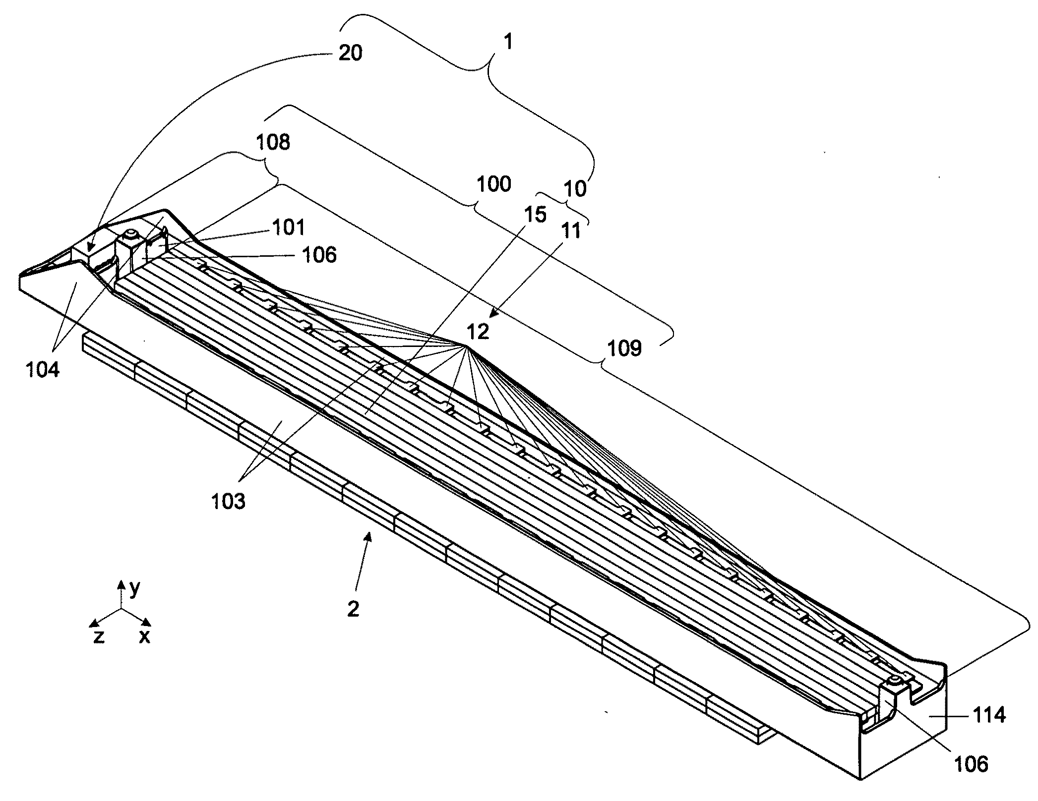
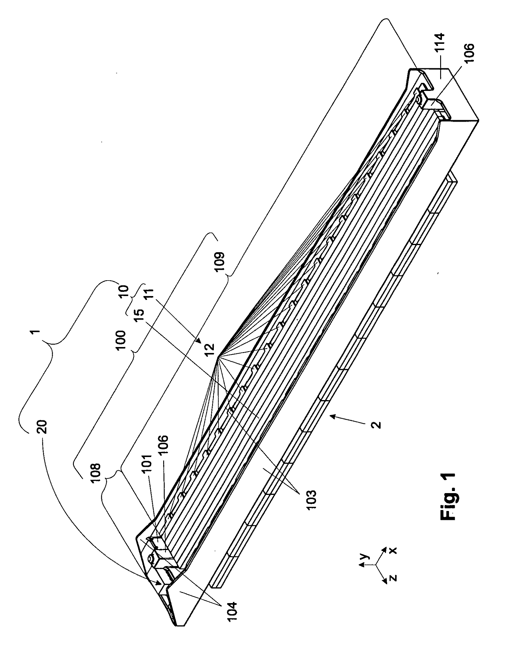
[0034]FIG. 1 is a stator 1 according to the invention together with a rotor 2. The rotor 2 comprises of a row of magnets or is made from magnetizable material. Usually, the rotor 2 is attached at a non-illustrated sliding door leaf.

[0035]The stator 1 comprises three parts: a stator member 10, a connecting member 20, and a holding member 100.

[0036]The stator member 10 has a coil arrangement 11, which is provided with a magnetic keeper 15 in a known manner. The stator member 10 generates an alternating magnetic field for moving the rotor 2 along a longitudinal extension of the stator member 10. In addition, if desired, it may assume a carrying function, for example with regard to a sliding door leaf to be moved.

[0037]The stator member 10 is received in the holding member 100. The holding member 100, seen in a longitudinal direction, i.e. in ±x-direction in FIG. 1, has two portions located one behind the other, a connecting member insertion portion 108 and a stator member insertion por...

second embodiment

[0059] shown in FIG. 5B, the pre-tensioning device is likewise formed by means of a spring projection 113′ cut out of the wall section 114 of the holding member 100. The spring projection 113′ is configured to protrude in a central area into the direction of the stator member 10 or of the connecting member 20. The difference to the embodiment shown in FIG. 5A is that the spring projection 113′ has no free end.

[0060]As an alternative, the pre-tensioning device 30 may be formed by a separately configured spring. According to a variant shown in FIG. 5C, it is preferably a spring element 113 configured as a hinge spring. However, it may as well be formed by means of a helical spring, as shown in FIG. 5D, which is propped up at the wall section 114.

[0061]Obviously, other spring arrangements are possible as long as they urge the stator member 10, respectively the connecting member 20 into the direction of the respective other member 20, or 10.

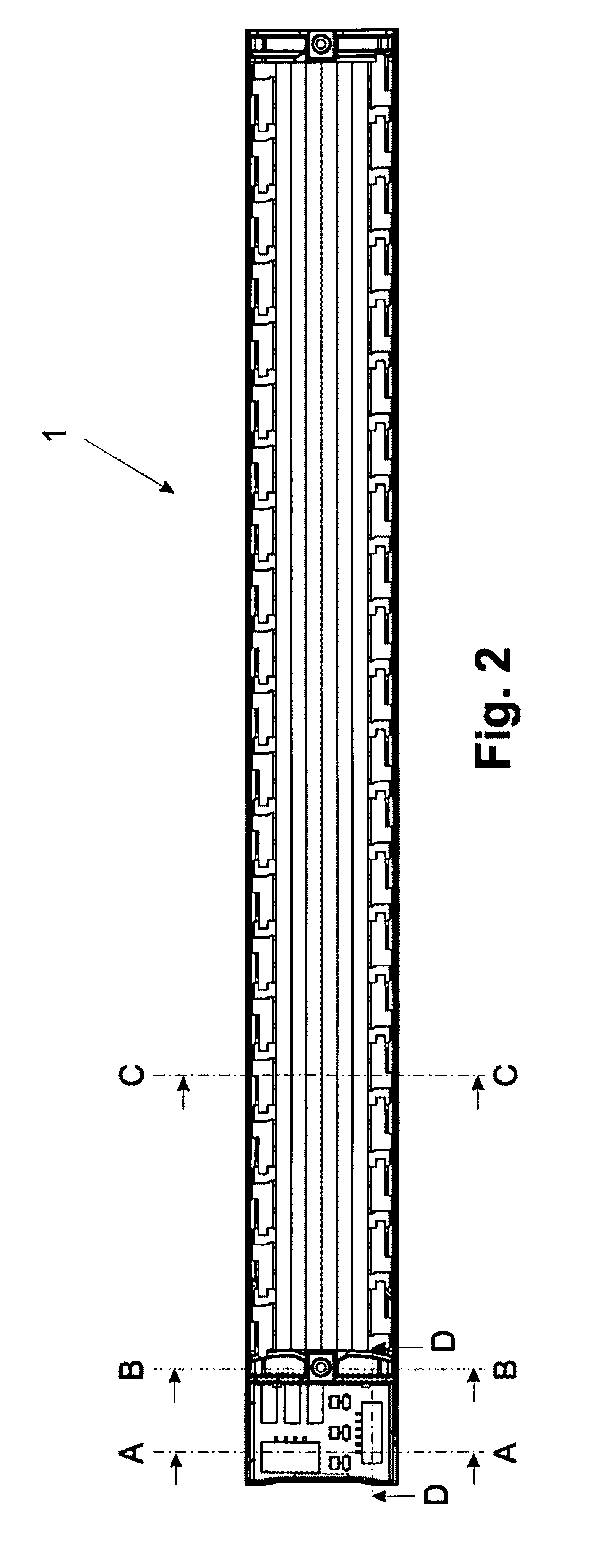
[0062]FIG. 6 shows a sectional view of the sta...


PUM


Abstract

A stator for a linear motor is described. The stator has a stator member with a coil arrangement, a connecting member with external terminals, a sensor arrangement having at least one Hall sensor, and terminals for the sensor arrangement, as well as a holding member. The holding member is subdivided into a connecting member insertion portion and a stator member insertion portion and has holding devices for disposing the stator member and the connecting member stationarily, releasably and in an accurate position with regard to each other.

Description

CROSS REFERENCE TO RELATED APPLICATION[0001]This is a U.S. national stage of application No. PCT / EP2008 / 006240, filed on Jul. 29, 2008. Priority is claimed on German Application No.: 10 2007 038 847.2, filed Aug. 16, 2007 the content of which is incorporated here by reference.BACKGROUND OF THE INVENTION[0002]1. Field of the Invention[0003]The invention relates to a stator of a linear motor, in particular for driving sliding doors.[0004]2. Description of the Related Art[0005]Linear drives for sliding door systems are well known. To determine a position of a sliding door leaf driven by a linear drive, Hall sensors, disposed within the stator, are used. Usually, they are incorporated into a coil arrangement of the stator of the respective linear motor.[0006]It is disadvantageous that, at the time of manufacturing the stator, the Hall sensors need to be incorporated into the coil arrangement. This circumstance leads to fact that the Hall sensors can not be tested separately from the coi...

Claims


Application Information

Patent Timeline
IPC IPC(8): H02K41/02E05F15/60
CPCH02K5/225H02K41/031H02K11/0073H02K11/0021H02K11/215H02K11/33
Inventor HUFEN, MICHAELRICHSTEIN, AXELSCHULER, THOMAS
Owner DORMAKABA DEUT GMBH
Learn More