Water detector

a detector and water technology, applied in the field of detector systems, can solve the problems of large amount of water, electrical corrosion and other forms of corrosion, and the disadvantages of the above mentioned methods

Inactive Publication Date: 2010-06-10
JOHNSEN ASLE INGEMAR
View PDF6 Cites 12 Cited by
  • Summary
  • Abstract
  • Description
  • Claims
  • Application Information

AI Technical Summary

Benefits of technology

[0006]According to the invention this objective is achieved by a detector system comprising one or more detection tracks arranged in a substantially fixed distance in a structure of a substantially insulating material, optionally in the embodiment as one or more fishing net like modules that can be connected together to other larger areas wherein each module comprises one net structure with one or more longitudinal detection tracks in one direction, optionally in two directions that are substantially normal to each other in such a way that a substantially rectangular structure is formed wherein each end or each of the four sides are terminated by a contact for attachment to adjacent similar modules, optionally end termination to a readout network. In a typical embodiment this structure is formed as wires on a foil material. In another embodiment this structure is embodied as a series of wires optionally intersecting each other wherein each intersection can optionally be stabilized using a stabilizing device.

Problems solved by technology

The disadvantageous of the above mentioned methods are numerous.
Solutions based on moisture absorbing materials will experience chemical corrosions of a time, optical methods require typically moistures at such levels that liquids will be present in free form, and devices based on electrical contact with water require relatively large amounts of water and may also experience problems with electrical corrosion and other forms of corrosion.
Costs are frequently major and are not suitable for large scale deployment.

Method used


Image

  • Water detector
  • Water detector

Examples


Embodiment Construction

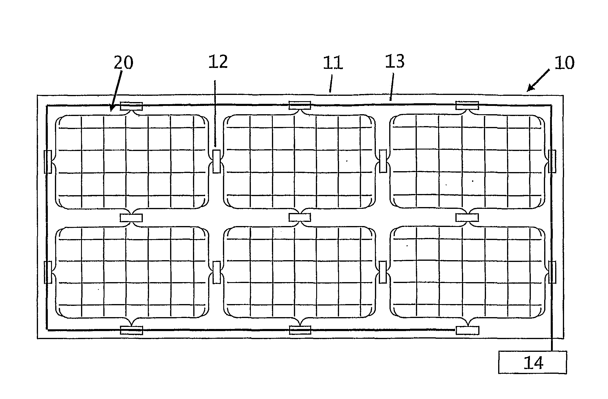
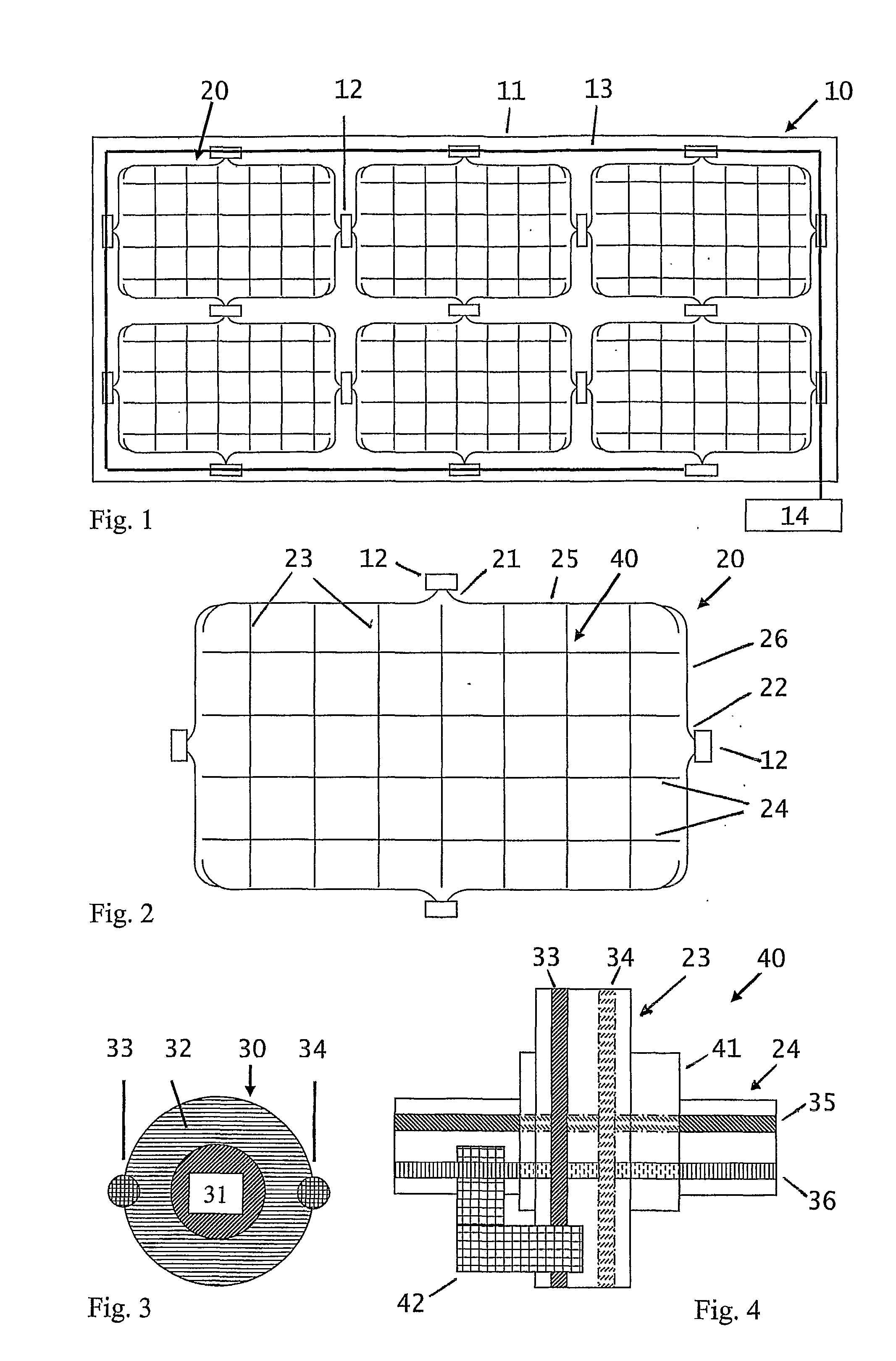
[0011]The invention will be disclosed with reference to the drawings wherein FIG. 1 shows the detector system in a typical embodiment. An installation 10 comprises six modules 20 in order to monitor an area 11. Each module 20 is interconnected with its nearest neighbour using a connection device 12. The modules 20 are also connected to a databus 13 which again conveys signals to a monitoring unit 14.

[0012]FIG. 2 shows a single module comprising a first end contact 21 which terminals a plurality of wires 23 using an interconnect 25. Correspondingly in a direction substantially perpendicular to the end contact 21 a second end contact 22 is provided, terminating plurality of wires 24 via an interconnect 26.

[0013]Such a module can be executed in a number of embodiments, in one embodiment as conductors on a substrate, typically embodied as printed conductors on for instance an acetate, a flexible foil suited for lying of the structures such as inside ceilings where the foil is transporte...


PUM

PropertyMeasurementUnit
mutual distanceaaaaaaaaaa
electricalaaaaaaaaaa
flexibleaaaaaaaaaa

Abstract

A detector system is provided suited for detection of environmental effects. The sensing element is constructed in the form of a grid and is designed in particular for the detection of moisture. Said structure is suited for simple deployment, optionally embedding into concrete, and detection of environmental effects on a large scale such as tunnels, bridges, dams and quays.

Description

CROSS REFERENCE TO RELATED APPLICATION[0001]This application claims priority to Norwegian Patent Application 2007 3343, filed 28 Jun. 2007.FIELD OF THE INVENTION[0002]This invention relates to a detector system comprising structures for detection of environmental effects.BACKGROUND[0003]From prior art one should refer to traditional moisture detectors such as detectors based on changes in electrical conductive properties of materials absorbing moisture, probes for capacity detection of moisture, optical detection of liquids and detection of liquids by short circuiting of electrodes. The disadvantageous of the above mentioned methods are numerous. Devices are typically hand held devices equipped with probes, put into direct contact with material to be investigated for moisture. Solutions based on moisture absorbing materials will experience chemical corrosions of a time, optical methods require typically moistures at such levels that liquids will be present in free form, and devices ...

Claims


Application Information

Patent Timeline
Patent Type & Authority Applications(United States)
IPC IPC(8): G01R27/08G01N27/04
CPCG01M3/047G01N27/121G01M3/165
Inventor JOHNSEN, ASLE INGEMAR
Owner JOHNSEN ASLE INGEMAR
Why Eureka
Try Eureka