
Video monitoring system

a video monitoring and video technology, applied in the field of video monitoring systems, can solve the problems of limited calculation resources assigned to network cameras, increased processing load, and difficulty in achieving video recognition with high, and achieve the effect of preferable efficiency

Inactive Publication Date: 2010-06-10
HITACHI INFORMATION & CONTROL SOLUTIONS LTD
View PDF6 Cites 97 Cited by
  • Summary
  • Abstract
  • Description
  • Claims
  • Application Information

AI Technical Summary

Benefits of technology

[0008]With the present invention, accomplished by taking the problems mentioned above into the consideration thereof, an object thereof is to provide a video monitoring system for enabling to lower or reduce the load of decoding process on the supervisor center side.
[0010]With the present invention mentioned above, in the image recognizer unit on the monitor apparatus side, since it is possible to select the decoding process depending upon recognition information on the camera side, and therefore achieving the video monitoring system having preferable efficiency thereof.

Problems solved by technology

The video monitoring system is constructed with a plural number of cameras and a controller apparatus and a recorder apparatus, but calculation resources assigned to the network cameras are limited, and it is difficult to achieve video recognition with high degree in many cases thereof.
In case where videos of the plural number of cameras are collected intensively to the monitor center, it is necessary to execute the decoding process, upon an enormous volume of videos, and then there occurs a problem that a processing load goes up.
In this manner, within the video monitoring system, there is the problem to be dissolved, i.e., achieving a desired process, effectively, among the limited processing resources thereof.

Method used


Image

  • Video monitoring system
  • Video monitoring system
  • Video monitoring system

Examples


Embodiment Construction

[0021]Hereinafter, embodiments according to the present invention will be fully explained by referring to the attached drawings.

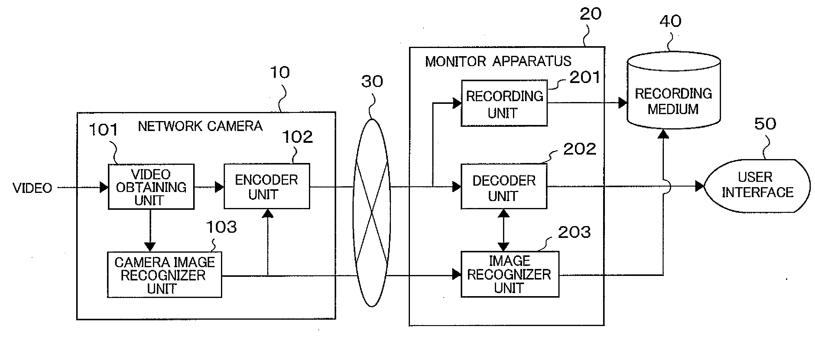
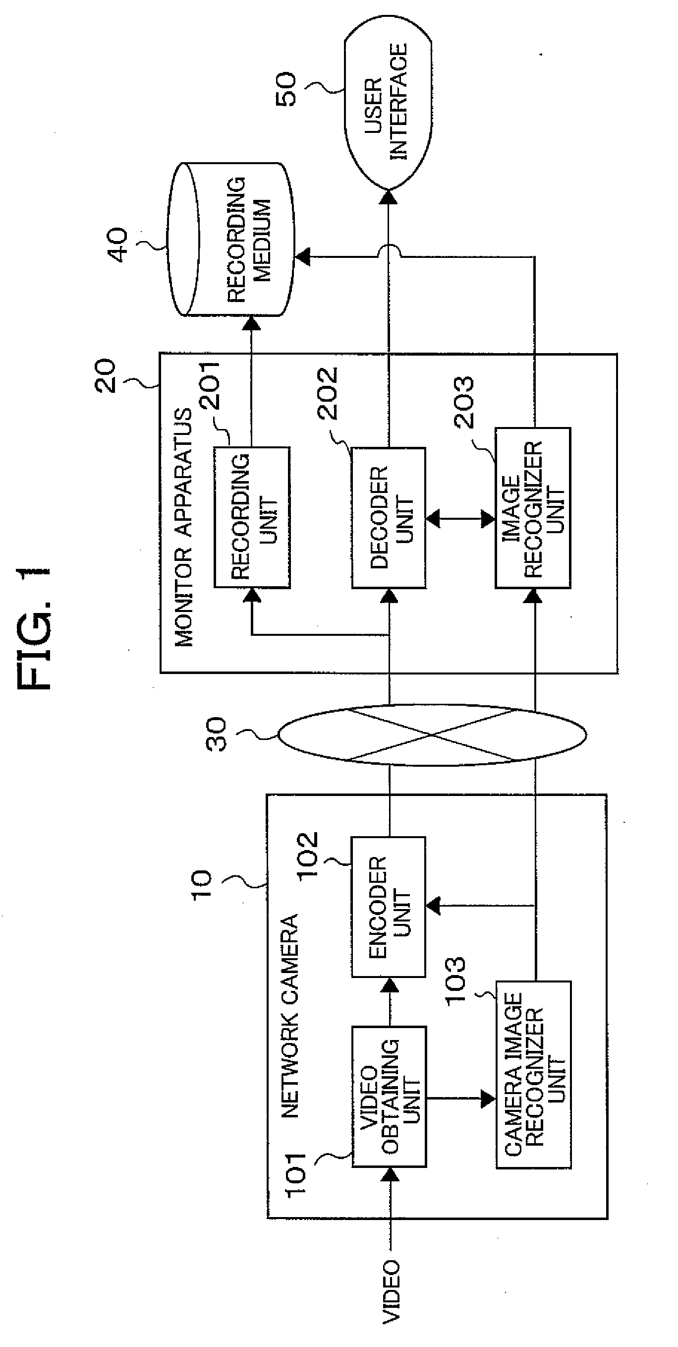
[0022]FIG. 1 shows the configuration of a video monitoring system of a network type, according to an embodiment of the present invention. In the present embodiment, hardwires are built up with an electronic computing system, including a CPU, a memory, a LSI, etc., thereby executing various kinds of functions. Herein, each function, being built up with, not a unit of the configuration of hardware, but hardware and software of those, is presented by a block.

[0023]The video monitoring system comprises a network camera 10 and a monitor apparatus 20, wherein videos and parameter information are transmitted through a network 30, from the network camera 10 to the monitor apparatus 20. As the network 30 may be used a personal circuit, which is owned by a user, or a public network. Also, communication protocol, etc., may be anything, as far as the present embodiment...


PUM


Abstract

A video monitoring system, comprises a camera, and a monitor apparatus, to which video data from the camera is transmitted, wherein the camera comprises a video obtaining unit for obtaining a signal from an image pickup device, a camera image recognizer unit for executing video processing upon an input video obtained from the video obtaining unit, an encoding unit for executing an encoding process upon basis of a result of the processing within the camera image recognizer unit, thereby producing the video data, and wherein the monitor apparatus comprises a decoding unit for decoding the video data, and an image recognizer unit for selecting a decoding means of the decoding unit, upon basis of the result of processing of the camera image recognizer unit.

Description

BACKGROUND OF THE INVENTION[0001]The present invention relates to a video monitoring system for detecting an invader from video, which is obtained from an image pickup apparatus, such as, a camera, etc.[0002]A video monitoring system, having a function of detecting a moving article, such as, a human being or a vehicle, etc., for example, appearing in a monitoring area, from video obtained from a camera, through video processing thereof, has further a function of recording only the video in which the moving article appears, and or a function of presenting an alarm icon on a display device, with using the result of detections, or it can call an attention of a watchman with buzzing a buzzer, therefore it is helpful for reducing load of a watching or observation job, conventionally necessitating a confirming operation by the watchman, always. Also, such video monitor system enables to use the video recorded, for the purpose of proving a crime after the fact, when an unfair practice occu...

Claims


Application Information

Patent Timeline
IPC IPC(8): H04N7/18
CPCG06K9/00771G06T7/2053G08B13/19671G06T2207/20224G06T2207/30232G06T2207/20144G06T7/254G06T7/194G06V20/52
Inventor ITOH, MASAYAMIYOSHI, MASANORIKAZUI, MASATOFUJII, HIROMASA
Owner HITACHI INFORMATION & CONTROL SOLUTIONS LTD
Features
  • Generate Ideas
  • Intellectual Property
  • Life Sciences
  • Materials
  • Tech Scout
  • Unparalleled Data Quality
  • Higher Quality Content
  • 60% Fewer Hallucinations
Learn More