
Image reader for use in an image forming apparatus, and contamination check method of guide film for the same

a technology for image forming apparatus and image reader, which is applied in the direction of lighting and heating apparatus, umbrellas, instruments, etc., can solve the problems of product instability, inconvenient distribution and handling of products, and unstable products so as to reduce the size of image forming apparatus

Inactive Publication Date: 2010-06-10
HEWLETT PACKARD DEV CO LP
View PDF9 Cites 5 Cited by
  • Summary
  • Abstract
  • Description
  • Claims
  • Application Information

AI Technical Summary

Benefits of technology

The solution reduces the size of the image reader, balances the image reading and forming parts, stabilizes the product, and allows for efficient packaging by eliminating unnecessary space, while the contamination checking unit ensures optimal performance and maintenance.

Problems solved by technology

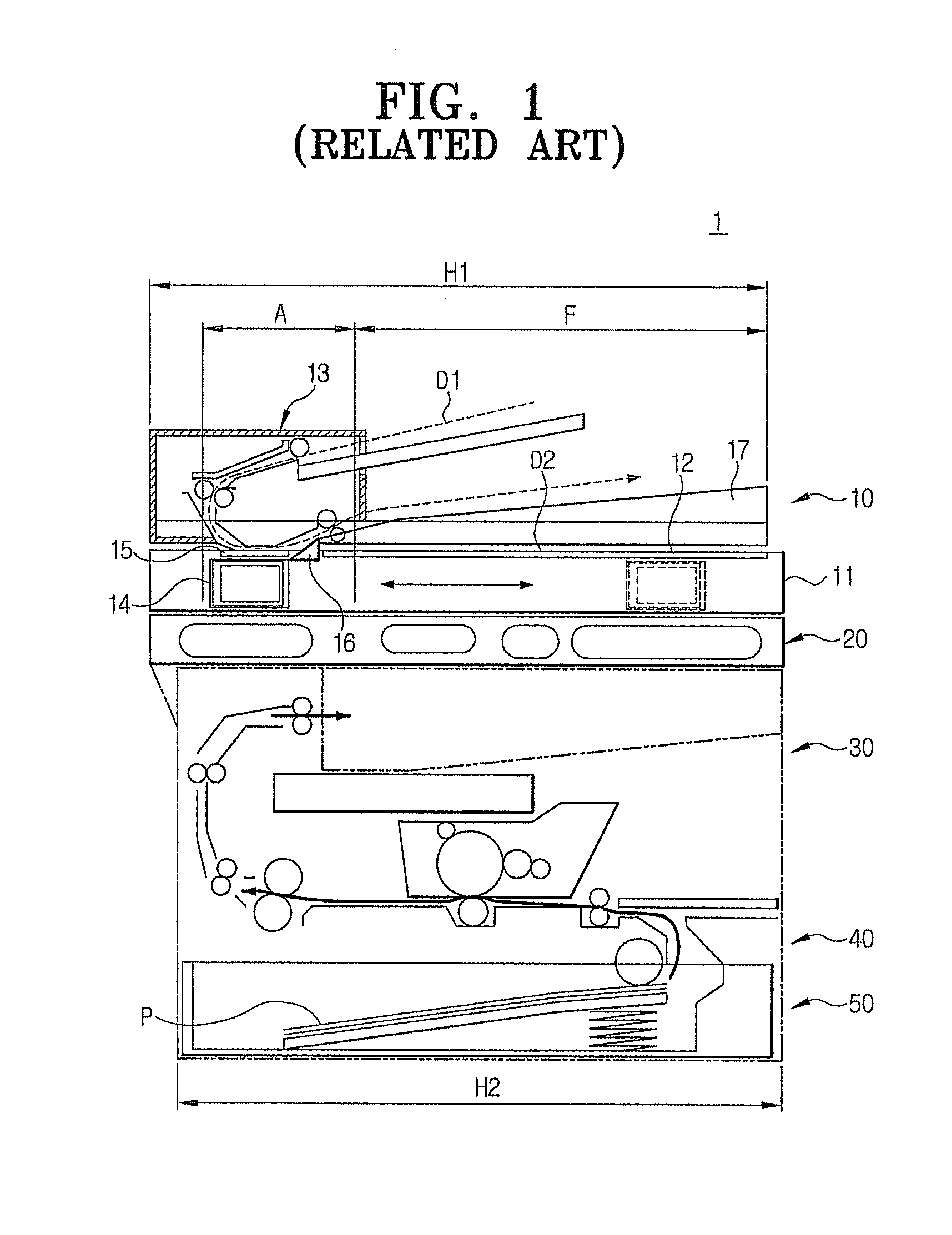
However, there are several problems associated with the arrangement shown in FIG. 1.
In addition, there has been another problem in that the width H1 of the image reader 10 is not similar to or identical with a width H2 of a lower part of the image former 30.
As a result, the product, i.e., image forming apparatus can be unstable since the image reader 10 can be much larger than the image former 30, or vice versa.
Further, there has been another problem in that, as the size of the image forming apparatus is increased, it is inconvenient to distribute and handle the product.
Thus, it is difficult to efficiently package the product, and the product is likely to be easily damaged against impact during distribution.

Method used


Image

  • Image reader for use in an image forming apparatus, and contamination check method of guide film for the same
  • Image reader for use in an image forming apparatus, and contamination check method of guide film for the same
  • Image reader for use in an image forming apparatus, and contamination check method of guide film for the same

Examples


Embodiment Construction

[0043]Reference will now be made in detail to the present embodiments of the present invention, examples of which are illustrated in the accompanying drawings, wherein like reference numerals refer to the like elements throughout. The embodiments are described below in order to explain the present invention by referring to the figures.

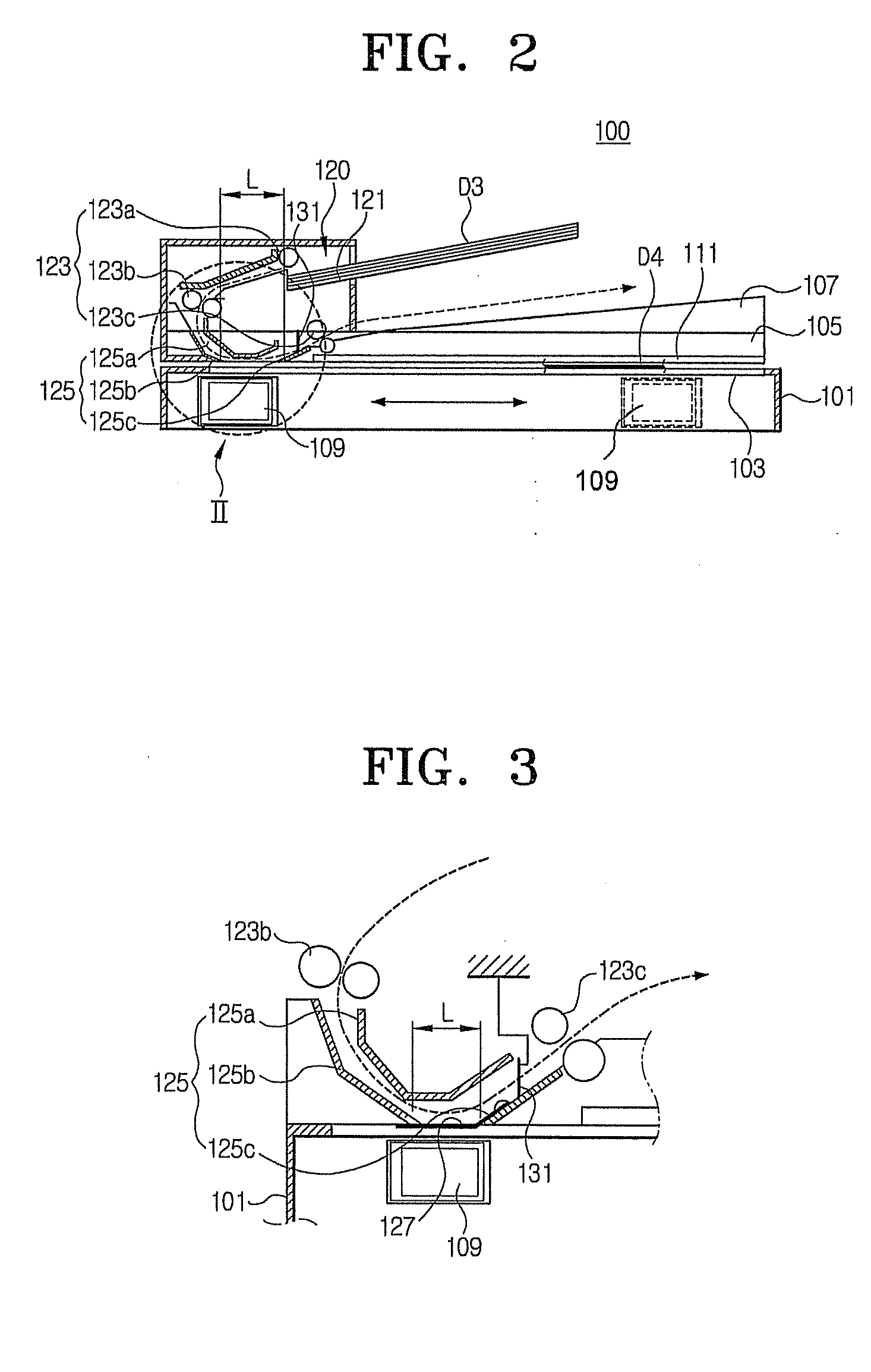
[0044]FIG. 2 is a schematic view of an image reader for use in an image forming apparatus according to an embodiment of the present invention.

[0045]Referring to FIG. 2, the image reader 100 for use in an image forming apparatus includes an image reading table (body) 101; a document glass 103 formed on a surface of the image reading table 101; a cover 105 secured at a distal end of the image reading table 101 to rotate about the distal end between an open position and a closed position so as to cover the image reading table 101; a document discharging plate 107 arranged as part of the cover 105 to receive individual sheets of paper, such as document D3,...


PUM


Abstract

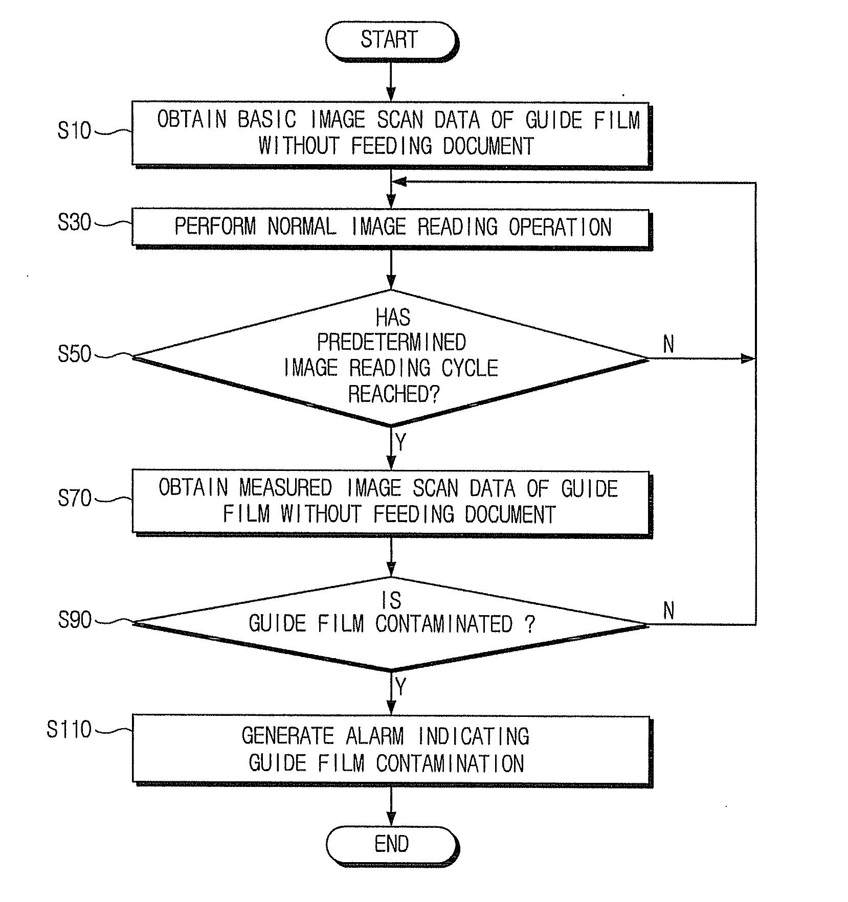
An image reading apparatus for use in an image forming apparatus includes a document glass installed on an upper side of the image reading body on which a document is placed; an image reading sensor installed under the document glass for stopping after being transferred to a predetermined position or for reciprocating in a straight direction parallel to the document glass; a cover for opening and closing the upper surface of the document glass; an automatic document feeder (ADF) for feeding the document to the position to which the image reading sensor is fixed; a document discharging plate for discharging the document fed through the automatic document feeding unit; first and second guide members for guiding to allow the document fed through the automatic document feeding unit to be discharged to the document discharging plate, the first and second guide members being installed at a predetermined interval to expose the document toward the image reading sensor; and a guide film installed to cover the interval between the first and second guide members for guiding to allow the document to be discharged to the document discharging plate. By this structure, a size of the image forming apparatus can be reduced.

Description

CROSS-REFERENCE TO RELATED APPLICATIONS[0001]This application is a continuation of U.S. Ser. No. 11 / 289,498, filed Nov. 30, 2005, the disclosure of which is incorporated by reference herein. This application claims all benefits accruing under 35 U.S.C. §119 from Korean Patent Application No. 2005-4792 filed on Jan. 19, 2005 in the Korean Intellectual Property Office, the entire content of which is incorporated by reference herein.BACKGROUND OF THE INVENTION[0002]1. Field of the Invention[0003]The present invention relates to an image forming apparatus and an image reader for use therein, and more particularly, to an image reader for use in an image forming apparatus to minimize the size of a scanning portion, via an Auto Document Feeder (ADF) scanning area and a flatbed scanning area, and a method for checking the contamination of a guide film.[0004]2. Related Art[0005]Generally, an image reader is included as part of an image forming apparatus, such as, a printer, a facsimile machi...

Claims


Application Information

Patent Timeline
Patent Type & Authority Applications(United States)
IPC IPC(8): H04N1/04
CPCH04N1/121H04N1/193H04N1/1235H04N1/123A45B3/04F21V33/0004F21V23/04A45B2200/1018F21V23/003
Inventor PARK, SANG-CHEOLKIM, YOUNG-MIN
Owner HEWLETT PACKARD DEV CO LP
Learn More