Portable device and portable watch
a technology of portable devices and watches, which is applied in the direction of electric winding, instruments, and horology, can solve the problems of poor workability of rotating locking members and the inability to operate locking members in a state, and achieve the effect of easy rotation and rarely hindering operation
- Summary
- Abstract
- Description
- Claims
- Application Information
AI Technical Summary
Benefits of technology
Problems solved by technology
Method used
Image
Examples
first embodiment
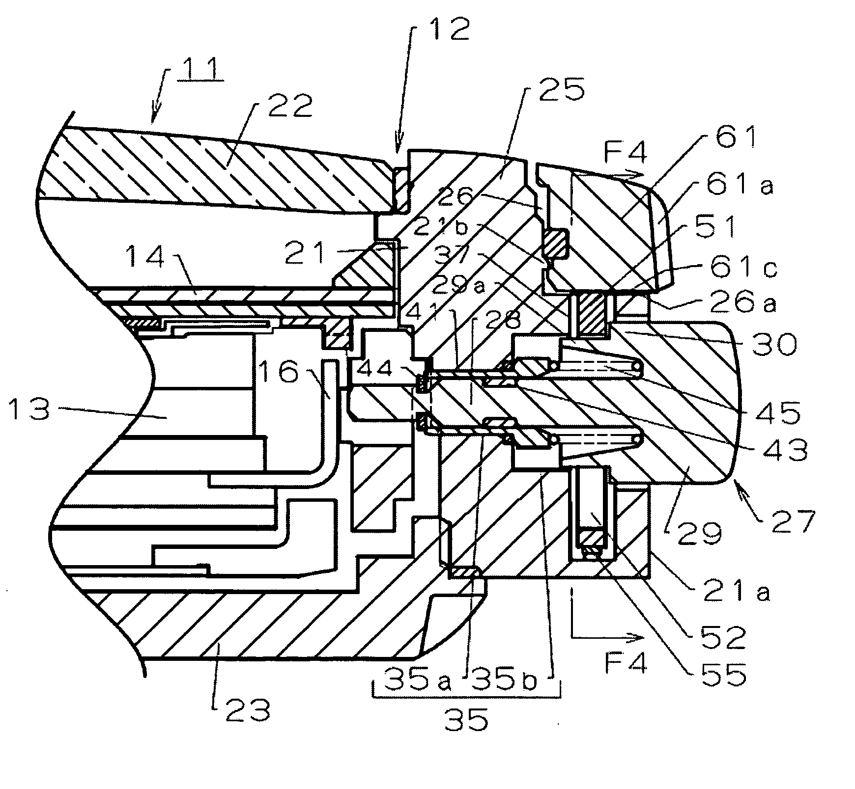
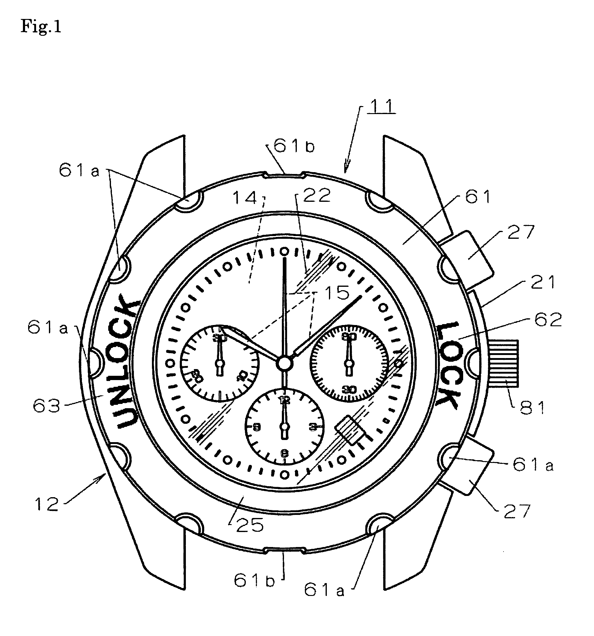
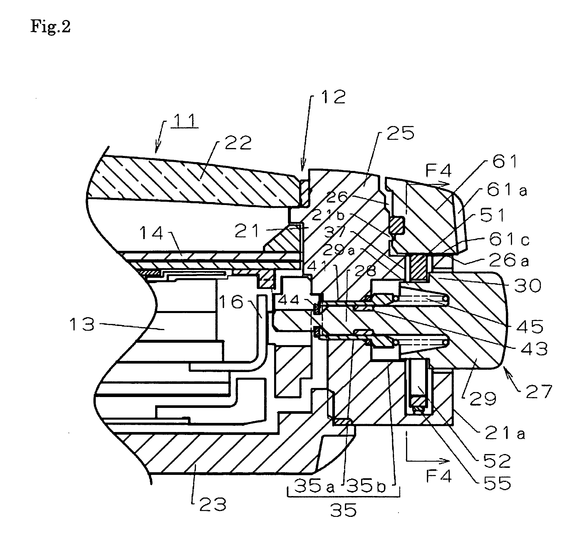
[0043]Referring now to FIG. 1 to FIG. 8, the present invention will be described.
[0044]Reference numeral 11 in FIG. 1 to FIG. 3 designates a portable device, for example, a portable watch, and more specifically, a wristwatch. A watch sheath 12 of the wristwatch 11, which constitutes a device sheath, includes a built-in component, for example, a watch movement 13 integrated therein, and a display portion, for example, a circular hour plate 14 is mounted thereon. The display of the hour plate 14 is indicated by time display hands 15 such as an hour hand, a minute hand, and a second hand driven by the watch movement 13.
[0045]The watch movement 13 includes a contact point 16 (see FIG. 2 and FIG. 3) formed of a leaf spring or the like. When the contact point 16 is pressed by a push button, described later, the function of the watch movement 13 is changed over.
[0046]The watch sheath 12 is formed by mounting a glass 22 for allowing a viewer to see the hour plate 14 therethrough on a surfac...
second embodiment
[0091]In the wristwatch 11 in a state in which the winder 81 is not used such as the case of being carried, the locking member 51 is arranged at the locked position in which the unintended pulling of the winder 81 outward and sideward of the body 21 is prevented as shown in FIG. 9.
[0092]In a state in which the winder 81 is locked by the locking means, the lock surface 61c of the operating ring 61 is in contact with the edge 51a (see FIG. 4 and FIG. 5) of the locking member 51, and hence the locking member 51 is pushed downward against the urging force of the leaf spring 55 and is arranged in the locked position shown in FIG. 9. The stopper portion 51b (see FIG. 4 and FIG. 5) of the lock member 51 arranged at this locked position is fitted into the engaging portion 85 which is a recess formed on the winder 81.
[0093]Therefore, when a pulling force acts accidentally on the winder 81 in the locked state, the stopper portion 51b of the lock member 51 is caught by a wall surface of the r...
PUM
 Abstract
Description
Claims
Application Information
 - R&D
- Intellectual Property
- Life Sciences
- Materials
- Tech Scout
- Unparalleled Data Quality
- Higher Quality Content
- 60% Fewer Hallucinations
Browse by: Latest US Patents, China's latest patents, Technical Efficacy Thesaurus, Application Domain, Technology Topic, Popular Technical Reports.
© 2025 PatSnap. All rights reserved.Legal|Privacy policy|Modern Slavery Act Transparency Statement|Sitemap|About US| Contact US: help@patsnap.com


