Apparatus and method for pseudo-inverse multiplexing/de-multiplexing transporting

a technology of pseudo-inverse multiplexing and transporting, applied in the direction of multiplex communication, time-division multiplexing, electrical apparatus, etc., can solve the problem of inefficient opu2e-10v mapping different client signals, inability to simultaneously map two or more client signal types coming from different networks, and limitation of having to replace a 100g-level optic module with a 40g-level optic modul

Inactive Publication Date: 2010-06-10
ELECTRONICS & TELECOMM RES INST
View PDF6 Cites 52 Cited by
  • Summary
  • Abstract
  • Description
  • Claims
  • Application Information

AI Technical Summary

Benefits of technology

[0023]The frame configuration information includes at least one among the determined tributary slot type, the number of tributary slots used for mapping, justification control information and timing control information.

Problems solved by technology

Furthermore, it is impossible to simultaneously map two or more client signal types coming from different networks.
However, it is inefficient that OPU2e-10v maps different client signals except 100GbE signals.
However, in this case, since OPU4e-4v is a 40G-level signal, there is limitation to have to replace a 100G-level optic module with a 40G-level optic module.
That is, it is impossible to transport even a 100G-level tributary signal through a single 100G optic module.
However, since an OPU4 signal has a fixed payload capacity of about 100G not so as to map any tributary signal more than 100G, there is a problem that a new frame and a new multiplexing method have to be defined whenever to map tributary signals more than 100G.

Method used


Image

  • Apparatus and method for pseudo-inverse multiplexing/de-multiplexing transporting
  • Apparatus and method for pseudo-inverse multiplexing/de-multiplexing transporting
  • Apparatus and method for pseudo-inverse multiplexing/de-multiplexing transporting

Examples


Embodiment Construction

[0051]The detailed description is provided to assist the reader in gaining a comprehensive understanding of the methods, apparatuses and / or systems described herein. Various changes, modifications, and equivalents of the systems, apparatuses, and / or methods described herein will likely suggest themselves to those of ordinary skill in the art. Also, descriptions of well-known functions and constructions are omitted to increase clarity and conciseness.

[0052]FIG. 6 shows an exemplary OTUk frame structure.

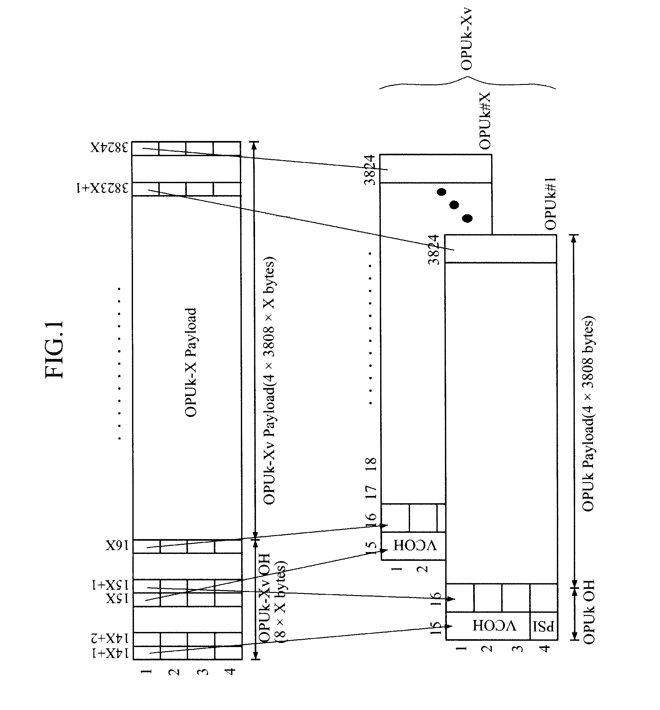
[0053]Referring to FIG. 6, the 15th and 16th columns of the OTUk frame correspond to an overhead. In the OTUk overhead, a Payload Structure Identifier (PSI) specifying a payload type is located at bytes on the 4th row of the 15th column. Bytes of the 16th column define an overhead required to map client signals to the OPUk payload. In the case of transporting a virtual concatenated signal, virtual concatenated overheads are additionally located at 3 bytes on the 1st to 3rd rows of the ...


PUM


Abstract

A pseudo-inverse multiplexing/de-multiplexing apparatus and method are disclosed. The pseudo-inverse multiplexing apparatus maps a client signal to an OPUk-Xpv signal. The OPUk-Xpv signal has a payload area that can be segmented into a plurality of tributary slots and an overhead area into which frame configuration information related to the tributary slots is inserted. The pseudo-inverse multiplexing apparatus decides the number of tributary slots to be used to map client signals, according to a bit rate or bit tolerance of the client signals, and maps the client signals using the determined number of tributary slots. Accordingly, it is possible to map or frame a variety of client signals.

Description

CROSS-REFERENCE TO RELATED APPLICATION[0001]This application claims the benefit under 35 U.S.C. §119(a) of Korean Patent Applications No. 10-2008-124171, filed on Dec. 8, 2008 and No. 10-2009-111560, filed on Nov. 18, 2009, the disclosures of which are incorporated by reference in its entirety for all purposes.BACKGROUND[0002]1. Field[0003]The following description relates to inverse multiplexing for optical communications.[0004]2. Description of the Related Art[0005]An optical transport network (OTN) uses time division multiplexing to map client signals having various bit rates to a single high speed frame and transport it. However, if a client signal to be mapped has a bit rate higher than a transport signal, inverse multiplexing is used to map a tributary signal having a high bit rate to several transport signal frames having relatively low bit rates.[0006]In view of signal capacity, the inverse multiplexing is basically to byte-interleave a large capacity of tributary signal int...

Claims


Application Information

Patent Timeline
Patent Type & Authority Applications(United States)
IPC IPC(8): H04J3/04H04J14/00
CPCH04J3/1652
Inventor SHIN, JONG-YOONKIM, JONG-HOKO, JE-SOO
Owner ELECTRONICS & TELECOMM RES INST
Why Eureka
Try Eureka