Self-suturing catheter system

a catheter hub and self-suturing technology, applied in the field of catheters, can solve the problems of troublesome suturing of the catheter hub to the skin, difficulty and time consumed, etc., and achieve the effect of convenient insertion and easy rotation

Inactive Publication Date: 2010-06-10
DANIELS JR RICHARD D +2
View PDF10 Cites 4 Cited by
  • Summary
  • Abstract
  • Description
  • Claims
  • Application Information

AI Technical Summary

Benefits of technology

[0008]Briefly described, a CON system in accordance with the present invention comprises a flexible catheter fixed to a catheter hub. The system may further include an insertion needle extending through the hub and catheter to facilitate insertion as in the prior art, but such a needle is incidental to the present invention which is directed specifically to an improved catheter hub.
[0009]The present invention consists in an improved catheter hub comprising a self-suturing mechanism for attaching the hub to the skin of a patient. The self-suturing mechanism includes a non-linear suturing needle, pivotably attached to the hub, which is easily rotated by an operator to engage an adjacent portion of the patient's skin. In a currently-preferred embodiment, a circular needle is rotatably slidable in a circular groove in the hub. The axis of the groove and needle may be coaxial with the the axis of the catheter or may be transverse thereto. Preferably, the needle is curved through more than 180° but less than 360° and is sharpened to a point at a first end and is formed into a tang at the opposite end. Alternatively, the hub may comprise first and second circular grooves disposed around a transverse axis and on opposite sides of the catheter/hub axis. In such an embodiment, the circular needle may comprise first and second circular portions disposed respectively in the

Problems solved by technology

A well-known operational problem in the use of prior art CON systems is the difficulty and time consumed in suturing the catheter hub to the skin.
This

Method used


Image

  • Self-suturing catheter system
  • Self-suturing catheter system
  • Self-suturing catheter system

Examples


Embodiment Construction

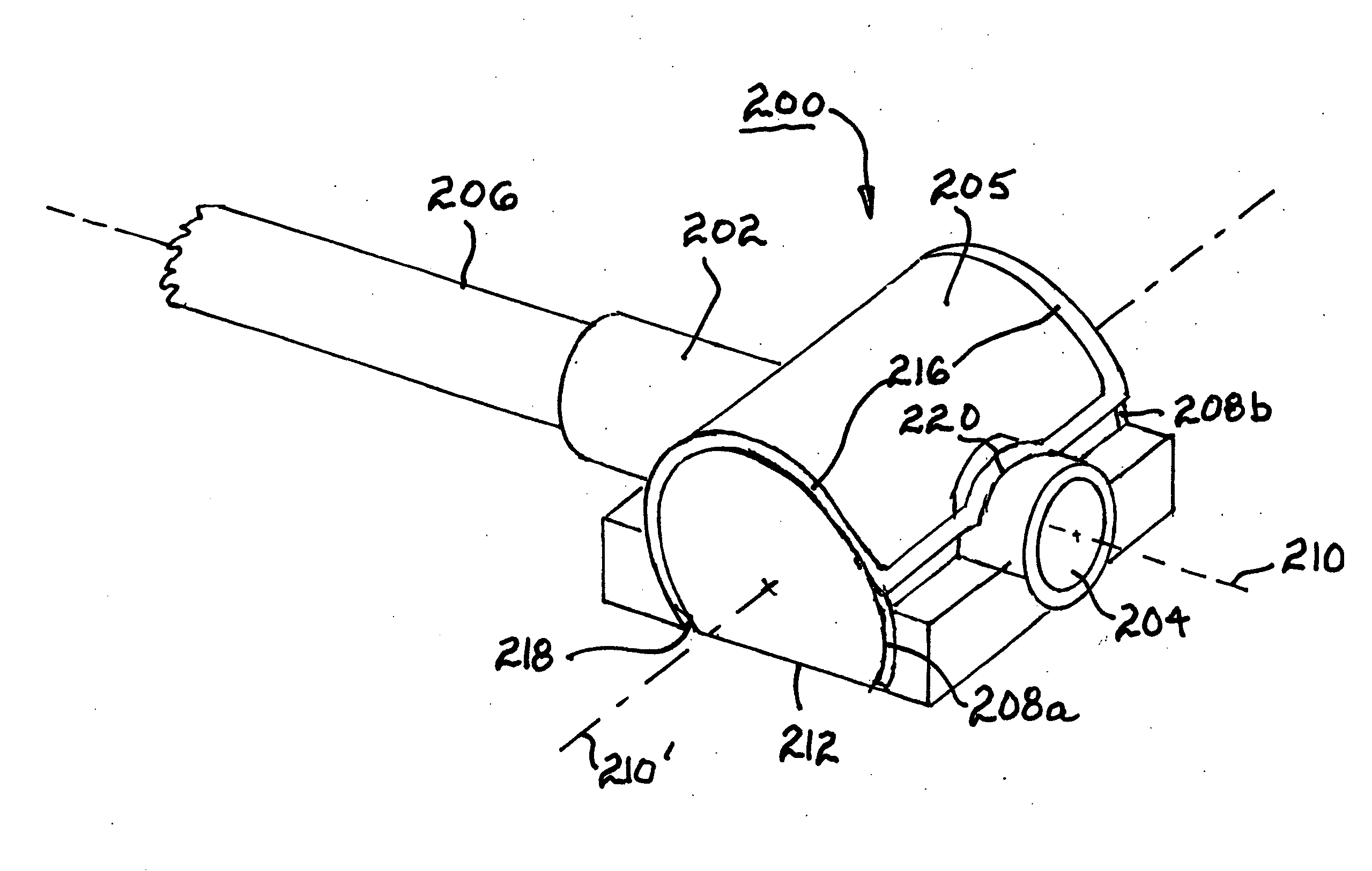
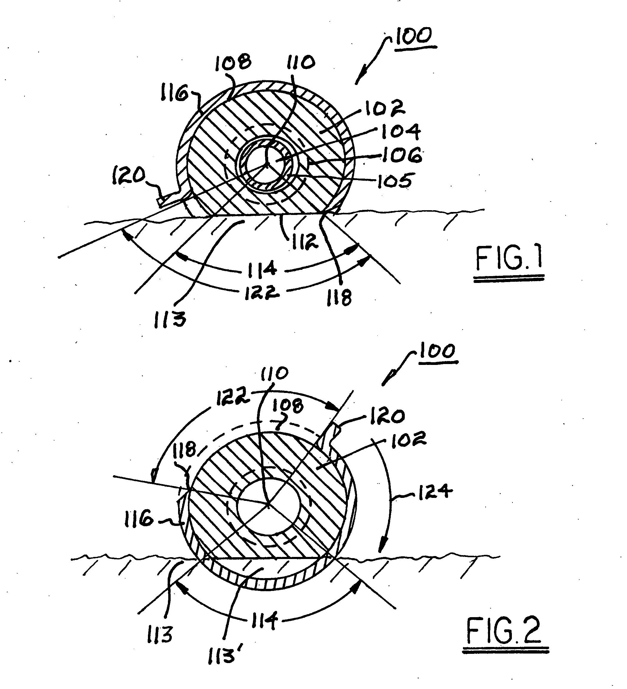
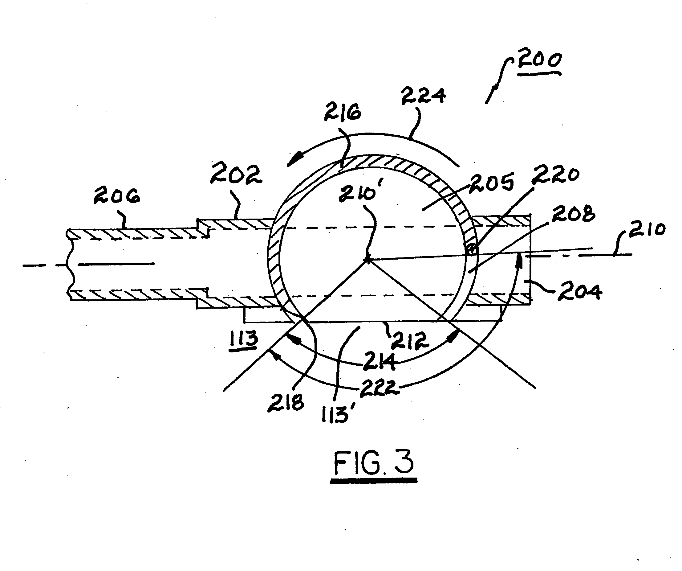
[0016]Referring to FIG. 1, in a first preferred embodiment 100 of an improved intravenous CON system, a catheter hub 102 includes a central opening 104 for passage of blood and / or medications, as well as for an optional insertion needle 105 as is known in the prior art. Opening 104 is coaxial with a catheter 106 attached to hub 102. Hub 102 further includes a circular groove 108 surrounding the axis 110 of hub 102. A flatted portion 112 defining a flat side of hub 102 truncates hub 102 and circular groove 108 through a central truncation angle 114. In use of system 100, flat side 112 rests against a patient's skin 113. A circular needle 116 ending in a sharp point 118 and an opposite-end tang 120 is slidably disposed in circular groove 108. Needle 116 preferably is curved through a central angle greater than 180°, the complementary central angle 122 preferably being greater than central truncation angle 114. Thus, when system 100 is placed for use against a patient's skin 113, prefe...


PUM


Abstract

An improved catheter-over-needle system having a hub including a self-suturing mechanism comprising a circular needle rotatably slidable in a circular groove in the hub. The needle is sharpened to a point at an end and preferably is also formed into a tang for use as a handle. The hub is flattened on a side to be adjacent to the skin, defining a hub flat thus truncating the groove through, for example 60° thereof. After the catheter is positioned in the blood vessel, the flat is pressed against the skin. The circular needle is rotated through an angle such that the circular needle passes through a portion of the skin, thereby “self-suturing” the hub to the skin of the patient. The hub is thus firmly attached to the patient, and no separate suturing is required. De-suturing of the catheter requires only reverse rotation of the circular needle.

Description

TECHNICAL FIELD[0001]The present invention relates to catheters for introducing medication into vascular systems of animals; more particularly, to intravenous catheters, especially veterinary catheters; and most particularly, to an improved intravenous catheter-over-needle system having a non-linear, pivotable, preferably circular needle for self-suturing of a catheter hub to skin at a point of catheter insertion without requiring separate suturing to maintain the catheter in place.BACKGROUND OF THE INVENTION[0002]Catheter-over-needle (CON) systems are well known in the medical arts for introducing medication into vascular systems of animals. A typical prior art CON system, such as the MILACATH Extended Use CON, available from Mila International, Inc., Erlanger, Ky., USA, comprises a flexible catheter tube mounted to a hollow catheter hub having laterally extending perforated wings. As delivered, the system includes a hollow rigid insertion needle extending through the hub and cathe...

Claims


Application Information

Patent Timeline
IPC IPC(8): A61M5/32
CPCA61M2025/0286A61M25/02
Inventor DANIELS, JR., RICHARD D.DANIELS, CYNTHIA B.BROWN, ROBERT C.
Owner DANIELS JR RICHARD D
Why Eureka
Try Eureka