Work Apparatus With Internal Combustion Engine

a technology of internal combustion engine and work apparatus, which is applied in the direction of mechanical apparatus, machines/engines, speed sensing governors, etc., can solve the problem that the air-fuel mixture fed by this operation is too rich to continue the explosion

Active Publication Date: 2010-06-17
YAMABIKO CORP
View PDF12 Cites 28 Cited by
  • Summary
  • Abstract
  • Description
  • Claims
  • Application Information

AI Technical Summary

Benefits of technology

The present invention relates to an improved design for controlling the operation of hydraulic power systems used in industrial machines such as excavators. One important feature of this new system is its ability to quickly respond to changes in engine speed during normal operating conditions without causing excessive wear on certain components. This results in better performance and durability of the machine's overall hydrautic power system.

Problems solved by technology

The technical problem addressed in this patent text is how to start an engine in a cold state using a choke valve and a throttle valve, and how to maintain the engine in a continuous rotation after starting it.

Method used


Image

  • Work Apparatus With Internal Combustion Engine
  • Work Apparatus With Internal Combustion Engine
  • Work Apparatus With Internal Combustion Engine

Examples


Embodiment Construction

[0070]Some preferred embodiments are explained below with reference to the drawings.

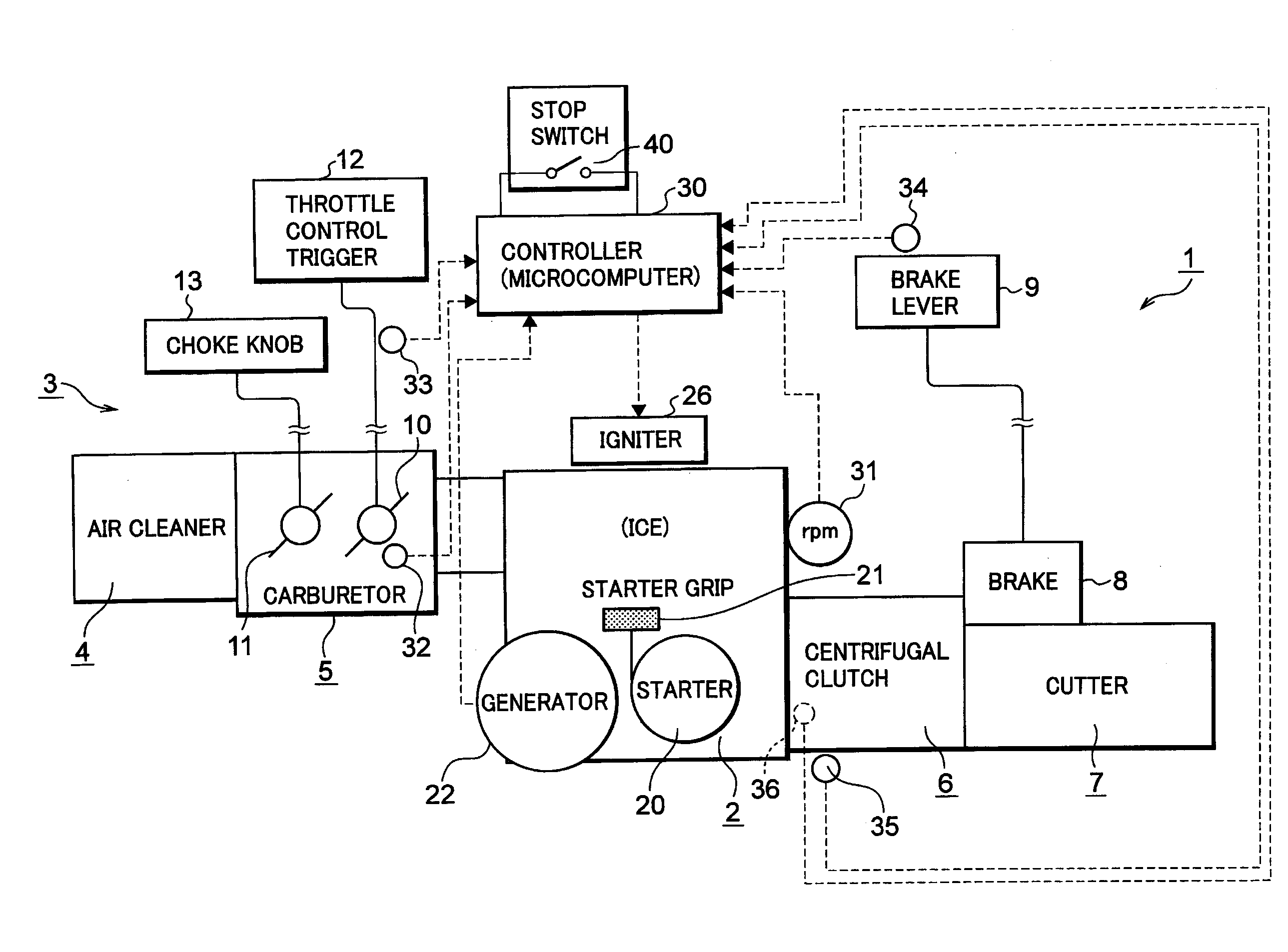
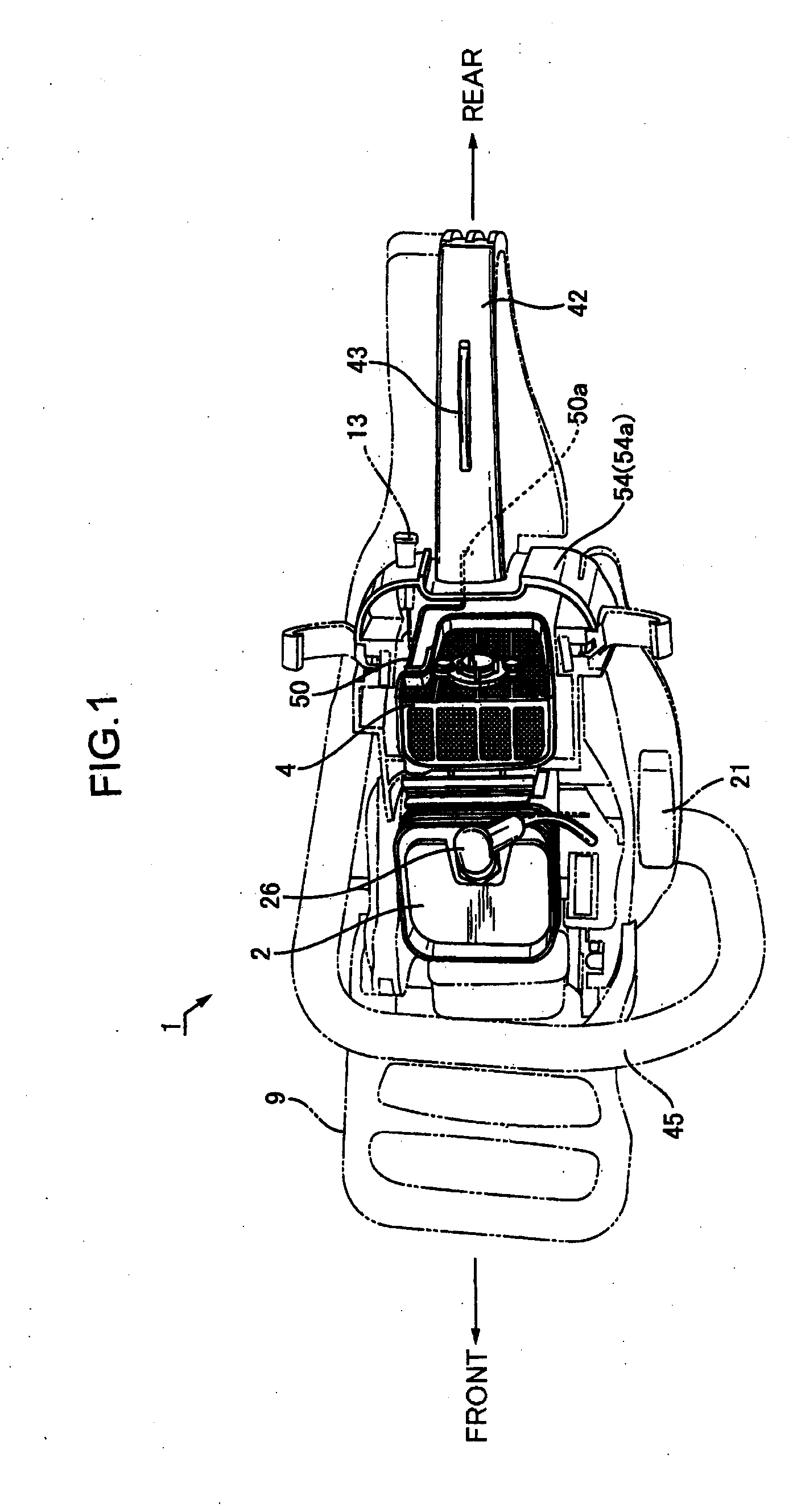
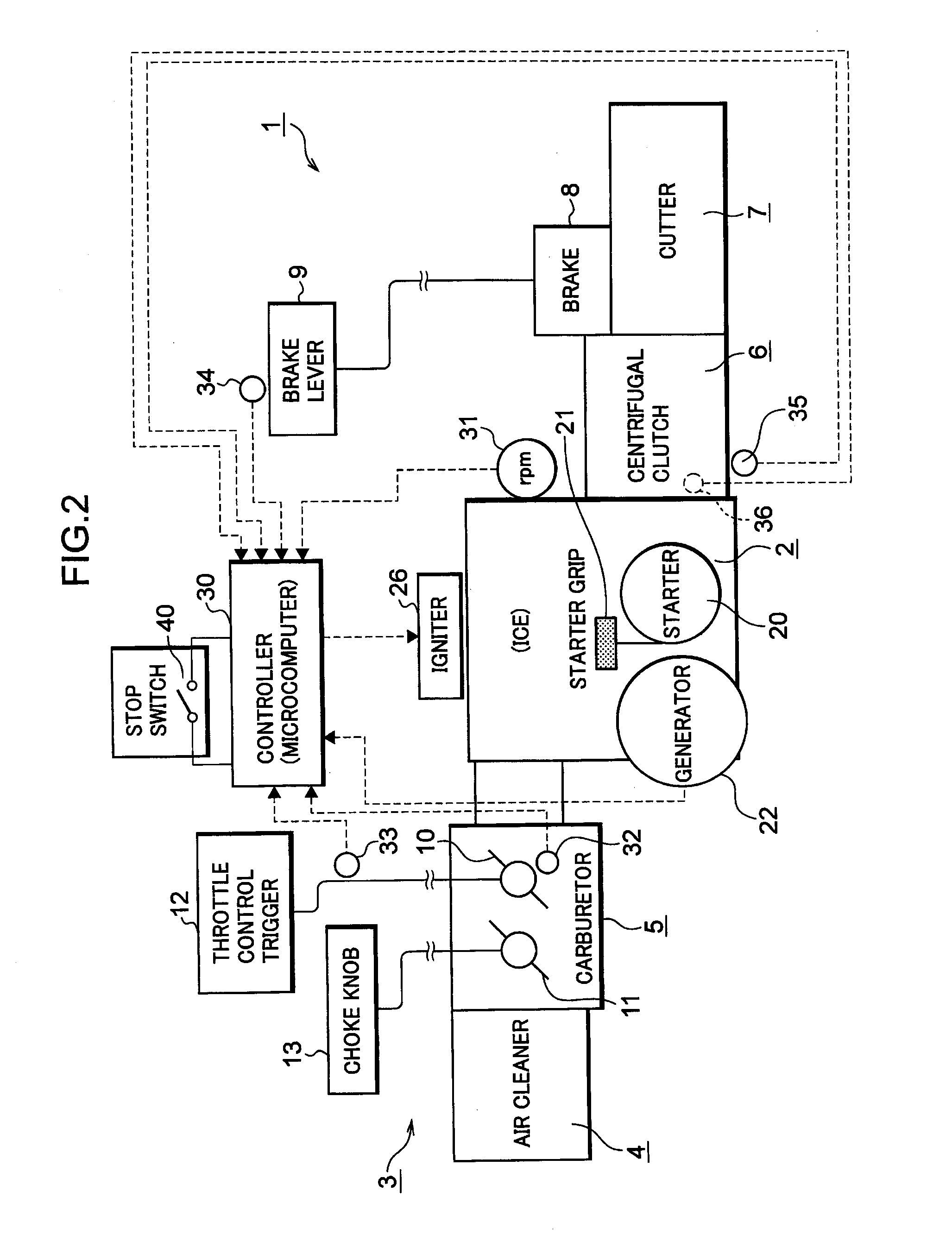
[0071]FIG. 1 is a plan view of a chain saw that is a work apparatus according to an embodiment of the invention. The chain saw of FIG. 1 is shown as not yet having attached a saw chain as a cutting element and with its upper cover removed to expose its engine and other components. FIG. 2 shows a basic configuration of the chain saw.

[0072]With reference to FIGS. 1 and 2, the chain saw 1 has a two-stroke single-cylinder engine 2. The engine 2 has an intake system comprising an air cleaner 4 at its upstream end and a carburetor 5 interposed between the air cleaner 4 and the engine 2. The engine 2 has an output shaft to which a centrifugal clutch 6 is connected. When engine revolution reaches and exceeds a predetermined reference revolution, power of the engine 2 is transmitted to a saw chain 7 via the centrifugal clutch 6.

[0073]The centrifugal clutch 6 is designed to get in engagement when the revolutio...


PUM


Abstract

Problems: For enhanced safety of a work apparatus with an internal combustion engine, a cutting element is prevented from an accidental run due to an accidental increase of the engine revolution while a throttle control trigger is in a released state.
Solution: In an engine start period, a throttle valve (10) is in a first idling position. The engine 2 at its initial run phase does not increase in revolution because of instability of its running condition. When the running condition begins to stabilize, the revolution rapidly increases. When the engine revolution (Ne) reaches 4,000 rpm or higher, a non-firing control mode is set up. In the non-firing control mode, when the engine revolution reaches or exceeds 4,500 rpm, a non-firing processing is executed (S4). A centrifugal clutch (6) is designed to engage at 5,000 rpm.

Description


Claims


Application Information

Patent Timeline
Owner YAMABIKO CORP
Why Eureka
Try Eureka