LED lighting device and driving method for the same

a technology of led lighting and driving method, which is applied in the direction of electric variable regulation, process and machine control, instruments, etc., can solve the problems of not revealing the luminance control of the illumination light at all, the chromaticity control range is too wide, and the control is complicated

Inactive Publication Date: 2010-06-17
IRIS OHYAMA
View PDF22 Cites 46 Cited by
  • Summary
  • Abstract
  • Description
  • Claims
  • Application Information

AI Technical Summary

Benefits of technology

[0011]According to one aspect of the present invention for achieving the above-mentioned purpose, it is provided that an LED lighting device comprises: a first light-emitting unit and a second light-emitting unit differing in a color temperature mutually; and a control circuit for executing a cyclic light/quench control of the first light-emitting unit and the second light-emitting unit so as to have a lighting period for lighting/quenching the first light-emitting unit and the second light-emitting unit complementarily, and a quenching period for quenching both the first light-emitting unit and the second light-emitting unit, and for executing a light control of the first light-emitting unit and the second light-emitting unit by a pulse number modulation control in a fixed cycle.
[0012]According to another aspect of the present invention, it is provided that an LED lighting device comprises: a first light-emitting unit and a second light-emitting unit differing in a color temperature mutually; and a control circuit for executing a light/quench control of the first light-emitting unit and the second light-emitting unit, the control circuit including a light/quench control unit for executing a cyclic light/quench control of the first light-emitting unit and the second light-emitting unit so as to have a lighting period for lighting/quenching the first light-emitting unit and the second light-emitting unit complementarily, and a quenching period for quenching both the first light-emitting unit and the second light-emitting unit, and a pulse number modulation control unit for executing a light control of the first light-emitting unit and the second light-emitting unit by a pulse number modulation control in a fixed cycle.
[0013]According to another aspect of the present invention, it is provided that an LED lighting device comprising: a first light-emitting unit and a second light-emitting unit differing in a color temperature mutually; and a control circuit for executing a cyclic light/quench control of the first light-emitting unit and the second light-emitting unit so as to have a lighting period for lighting/quenching the first light-emitting unit and the second light-emitting unit complementarily, and a quenching period which quenching both the first light-emitting unit and the second light-emitting unit, and for executing a variable control of the ratio between the lighting period of the first light-emitting unit and the lighting period of the second light-emitting unit in the lighting period according to a difference of inverse correlated color temperature of the first light-emitting unit and the second light-emitting unit.
[0014]According to another aspect of the present invention, it is provided that an LED lighting device comprises: a first light-emitting unit and a second light-emitting unit differing in a color temperature mutually; and a control circuit for executing a cyclic light/quench control of the first light-emitting unit and the second light-emitting unit so as to have a lighting period for lighting/quenching the first light-emitting unit and the second light-emitting unit complementarily, and a quenching period quenching both the first l

Problems solved by technology

However, persistently, the conventional technology of Patent Literature 1 calibrates the chromaticity of the illumination light by controlling a driving current of the white LEDs 65, and is not necessarily wide about its chromaticity control range.
Moreover, in the conventional technology of Patent Literature 1, since the both sides of the driving current of the white LEDs 65 and the on dut

Method used


Image

  • LED lighting device and driving method for the same
  • LED lighting device and driving method for the same
  • LED lighting device and driving method for the same

Examples


first embodiment

Led Lighting Device

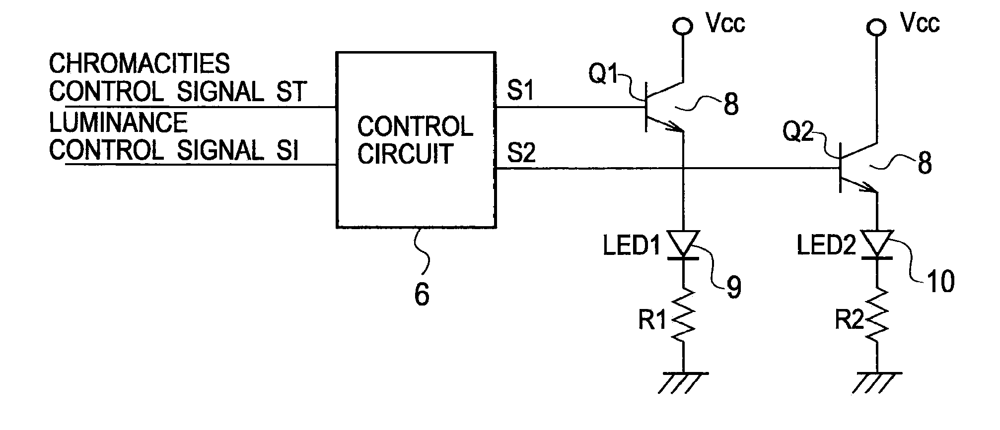
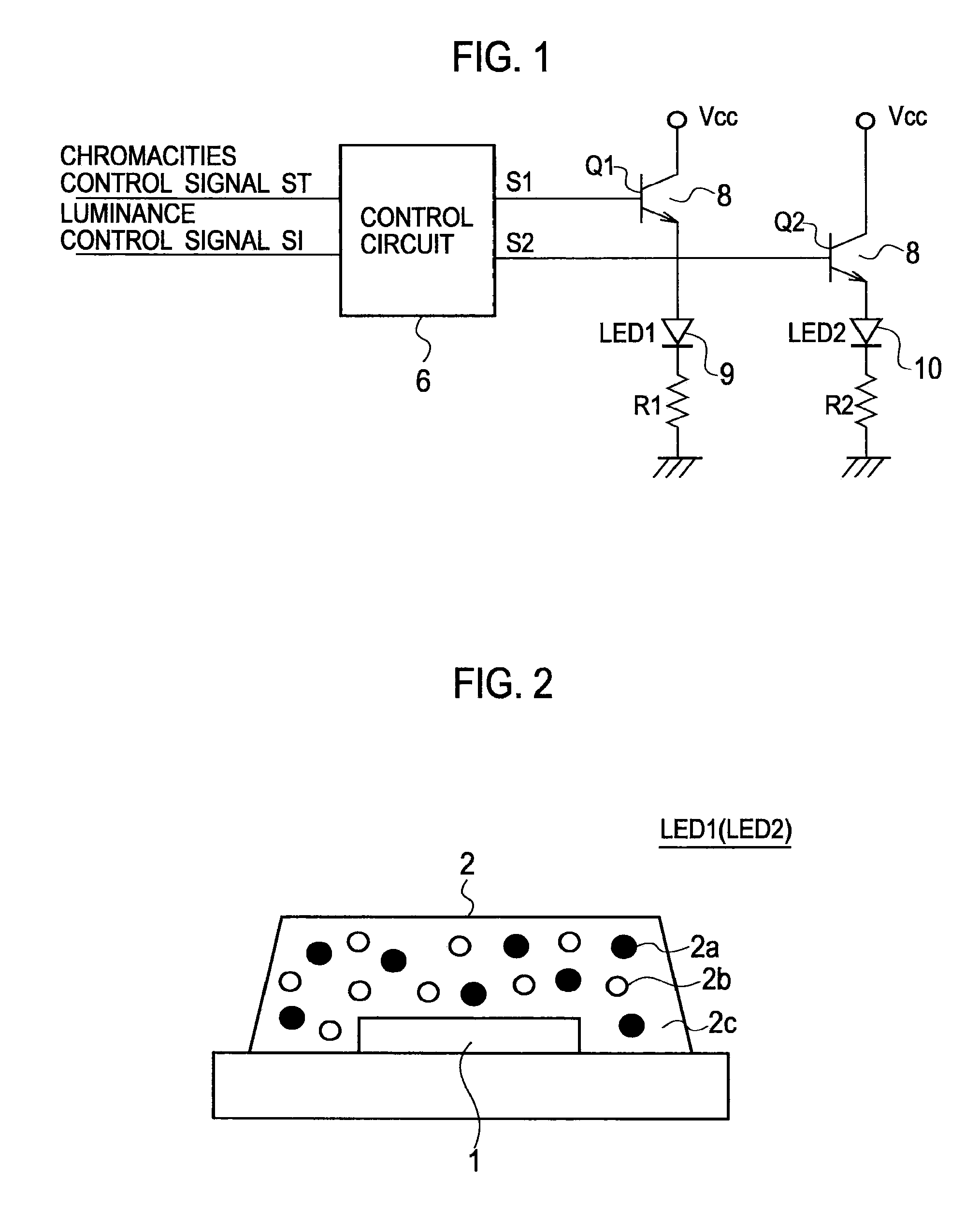
[0074]As shown in FIG. 1, an LED lighting device according to a first embodiment of the present invention includes a first light-emitting unit 9 and the second light-emitting unit 10 which differ in a color temperature mutually, and a control circuit 6 for executing light / quench control of the first light-emitting unit 9 and the second light-emitting unit 10.

[0075]The control circuit 6 executes a cyclic light / quench control of the first light-emitting unit 9 and the second light-emitting unit 10 so as to have the lighting period Ton for lighting / quenching the first light-emitting unit 9 and the second light-emitting unit 10 complementarily, and the quenching period Toff for quenching both the first light-emitting unit 9 and the second light-emitting unit 10. Furthermore, the control circuit 6 executes a light control of the first light-emitting unit 9 and the second light-emitting unit 10 by PNM (Pulse Number Modulation) control in the fixed cycle TN. Although the...

second embodiment

[0141]An LED lighting device according to a second embodiment of the present invention is only that the timing chart of the chromaticity control operation and luminance control operation differs from the LED lighting device according to the first embodiment, and the fundamental circuit configuration is the same as that of FIG. 1. Moreover, a detailed circuit configuration is also the same as that of FIG. 7A to FIG. 10C. The PNM control is applied as well as the LED lighting device according to the first embodiment.

[0142]Moreover, as shown in FIG. 12 to FIG. 14B, it is the same as that of the LED lighting device according to the first embodiment about a circuit block configuration of the LED drive circuit system in the case of mounting by adjoining two LED columns from which the color temperature differs, a circuit block configuration in the case of mounting by adjoining two LED columns from which the color temperature differs, and arraying the n-pairs, etc. Accordingly, the explanat...

third embodiment

[0156]An LED lighting device according to a third embodiment of the present invention is only that the timing charts of the chromaticity control operation and luminance control operation differ from the LED lighting device according to the first embodiment, and the fundamental circuit configuration is the same as that of FIG. 1. Moreover, a detailed circuit configuration is also the same as that of FIG. 7A to FIG. 10C. Furthermore, the PNM control is applied as well as the LED lighting device according to the first embodiment.

[0157]Moreover, as shown in FIG. 12 to FIG. 14B, it is the same as that of the LED lighting device according to the first embodiment about a circuit block configuration of the LED drive circuit system in the case of mounting by adjoining two LED columns from which the color temperature differs, a circuit block configuration in the case of mounting by adjoining two LED columns from which the color temperature differs, and arraying the n-pairs, etc. Accordingly, ...


PUM


Abstract

It is provided an LED lighting device calibratable to 0 to 100% of wide range about a chromaticity and luminance of a illumination light by a simple configuration, and a driving method for the LED lighting device. The LED lighting device is provided with a first light-emitting unit and a second light-emitting unit differing a color temperature mutually, and a control circuit for executing a cyclic light/quench control of the first light-emitting unit and the second light-emitting unit, and for executing a light control of the first light-emitting unit and the second light-emitting unit by a PNM (Pulse Number Modulation) control in a fixed cycle so as to have a lighting period Ton for lighting/quenching the first light-emitting unit and the second light-emitting unit complementarily, and a quenching period Toff for quenching both the first light-emitting unit and the second light-emitting unit.

Description

TECHNICAL FIELD[0001]The present invention relates to an LED lighting device applying an LED (Light Emitting Diode) as a light source, and a driving method for the same, and in particular relates to an LED lighting device for performing a chromaticity control and a luminance control of illumination light, and a driving method for the same.BACKGROUND ART[0002]As shown in FIG. 36, an LED lighting device according to a conventional example can calibrate the chromaticity and luminance of a illumination light of white LEDs 65 by controlling a level of a current supplied to a white LEDs 65 by a current value control circuit 62 and a power supply for driving LEDs 61, and controlling a ratio of the ON time and OFF time of the current supplied to the white LEDs 65 by the switch 64, a duty cycle ratio control circuit 66, and a PWM (Pulse Width Modulation) wave generation circuit 63 (for example, refer to Patent Literature 1).[0003]However, persistently, the conventional technology of Patent L...

Claims


Application Information

Patent Timeline
IPC IPC(8): H05B37/00H05B44/00
CPCH05B33/0818H05B33/0821H05B33/0827H05B33/0857Y02B20/346H05B37/02H05B33/0863H05B45/40H05B45/20H05B45/46H05B47/10Y02B20/30
Inventor MIZUNO, JUN
Owner IRIS OHYAMA
Why Eureka
Try Eureka