Escape Path Marking for an Aircraft

a technology for aircraft and exit path, applied in the direction of mass transit vehicle lighting, instruments, mobile visual advertising, etc., can solve the problem of no longer providing rectangular furniture, but furniture with curved contours

Inactive Publication Date: 2010-06-17
LUFTHANSA TECH AG
View PDF7 Cites 5 Cited by
  • Summary
  • Abstract
  • Description
  • Claims
  • Application Information

AI Technical Summary

Benefits of technology

[0013]The object of the present invention is to provide an escape path marking which may be adapted

Problems solved by technology

In particular, there is a trend no longer to provide re

Method used


Image

  • Escape Path Marking for an Aircraft
  • Escape Path Marking for an Aircraft
  • Escape Path Marking for an Aircraft

Examples


Embodiment Construction

[0034]While this invention may be embodied in many different forms, there are described in detail herein a specific preferred embodiment of the invention. This description is an exemplification of the principles of the invention and is not intended to limit the invention to the particular embodiment illustrated.

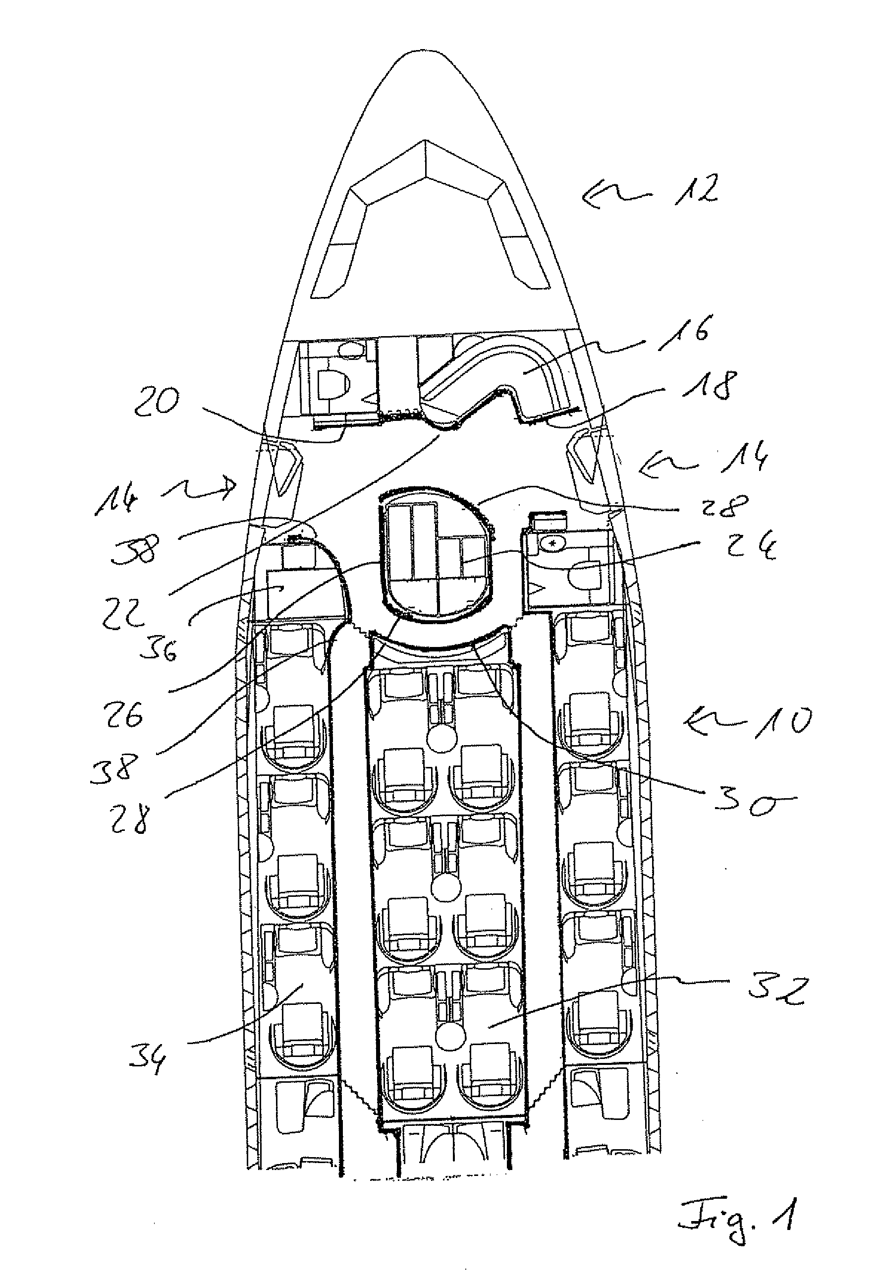
[0035]FIG. 1 shows a front portion of an aircraft with a passenger cabin 10 and a cockpit 12. In the front region of the passenger cabin 10, two doors 14 are provided to the side, which also serve for the emergency exit.

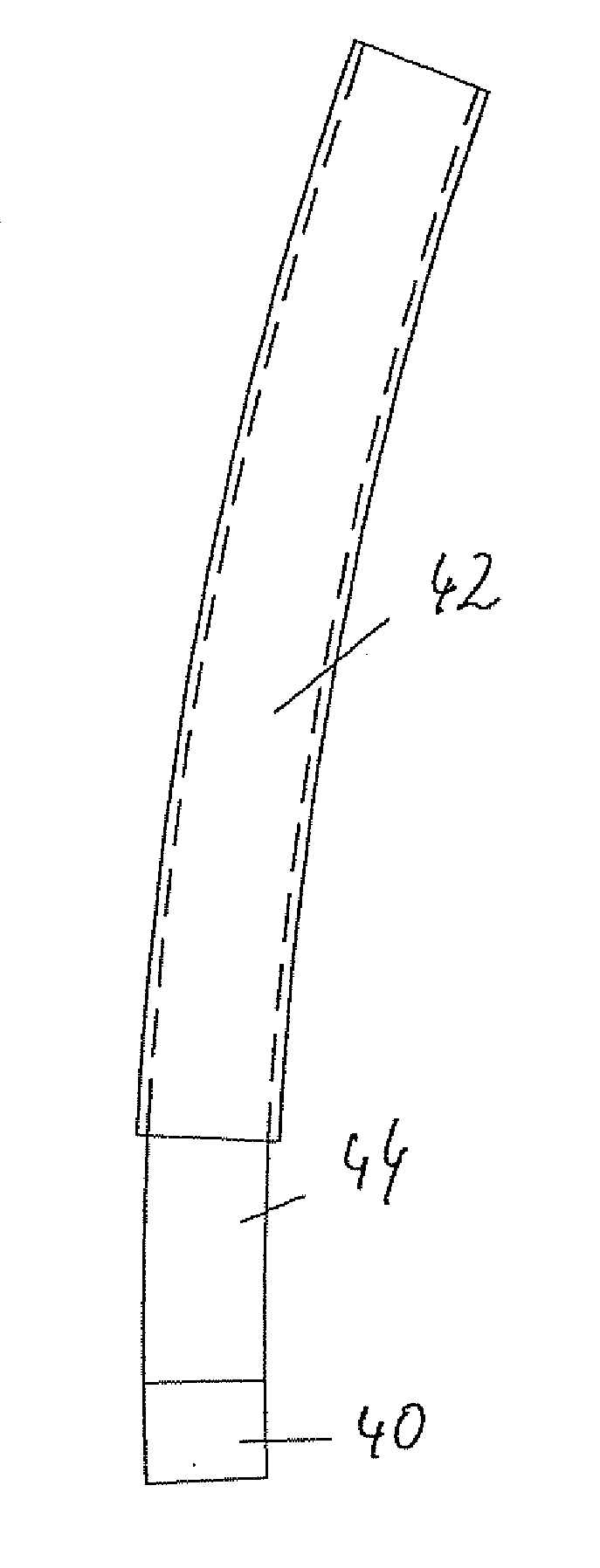
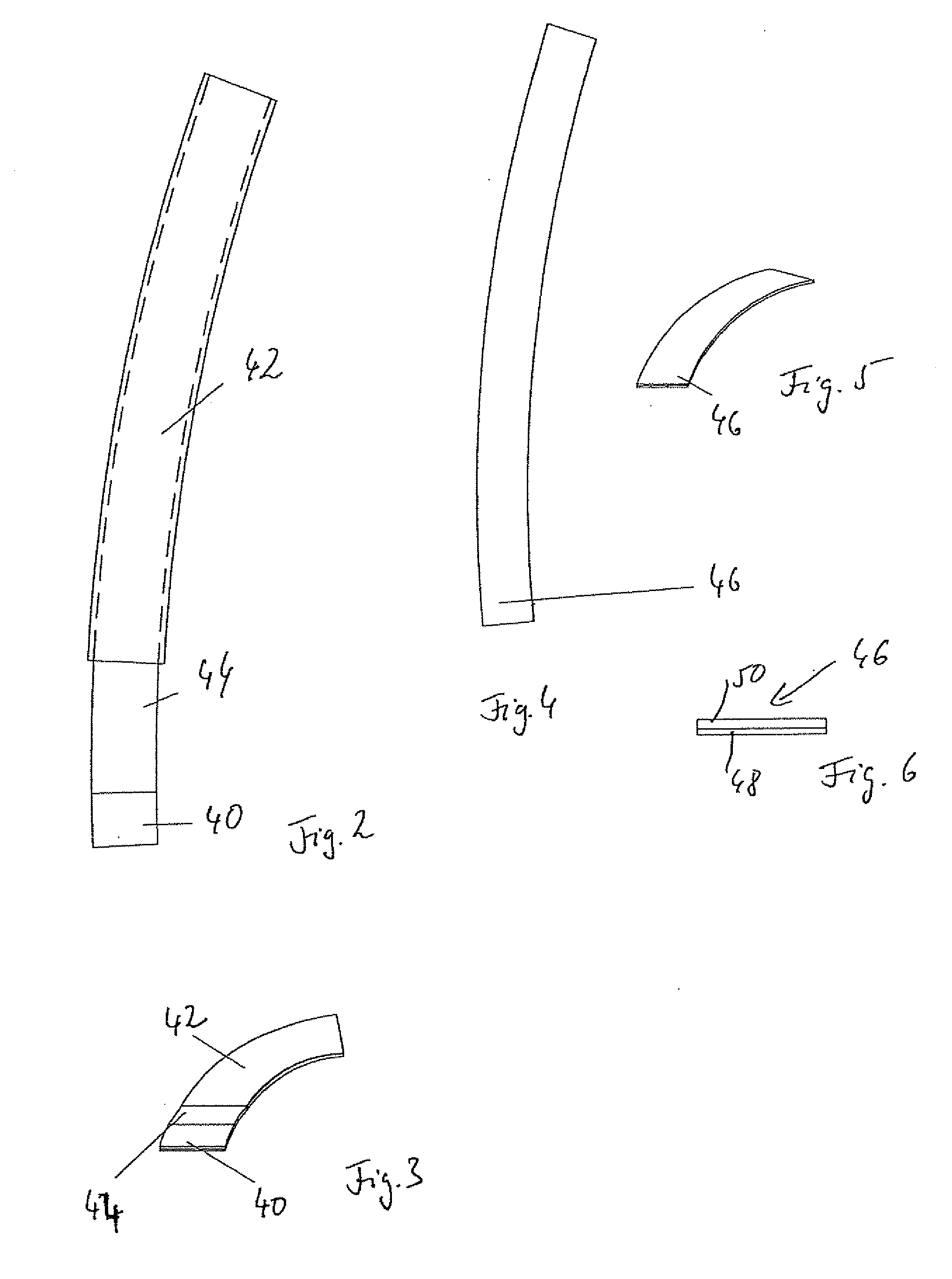
[0036]In the region between the passenger cabin 10 and the cockpit 12, a row of furniture and built-in components 16 is provided. The furniture and built-in components 16 are arranged in front of the exit doors 14. The front edge of the furniture and built-in components 16 is marked by an escape path marking 18. The escape path marking 18 has a row of straight portions 20 which alternate with bent portions 22.

[0037]The escape path marking 18 is made up of the ...


PUM


Abstract

Escape path marking for aircraft, which has an afterglowing photoluminescing material which is placed in several elements on the floor, characterised in that at least one element has a bent shape.

Description

CROSS-REFERENCE TO RELATED APPLICATIONS[0001]Not applicableSTATEMENT REGARDING FEDERALLY SPONSORED RESEARCH[0002]Not applicableBACKGROUND OF THE INVENTION[0003]The present invention relates to an escape path marking for an aircraft.[0004]It is known to arrange photoluminescent strips on the floor of the aircraft for escape path marking in aircraft, which is also denoted as emergency marking. Photoluminescence is occasionally also denoted as afterglow and / or phosphorescence. The safety requirements are, for example, specified in the German Industry Standard DIN 67 510. The strips are laid in a straight line in the floor and direct the passengers and crew in the event of an emergency to the doors and emergency exits. In the past, photoluminescent strips have become increasingly accepted in the design of aircraft, as said strips are fail-safe and may be operated without a power supply.[0005]An emergency lighting system is known, for example, from WO 96 / 33093 A1, in which a photolumines...

Claims


Application Information

Patent Timeline
IPC IPC(8): F21S8/10
CPCA62B3/00B60Q3/0256B60Q3/0289G09F21/06G09F13/20G09F19/22B64D25/08B64D47/04B60Q3/46B60Q3/78
Inventor SUTTER, WOLFGANG
Owner LUFTHANSA TECH AG
Why Eureka
Try Eureka