Target tracker

a tracking device and target object technology, applied in the field of tracking devices, can solve the problems of inability to cope with sudden changes of apparent colors, inability to use initial set colors of target objects in continued tracking, and inability to always be effective for tracking precision enhancement upon apparent color changes

Active Publication Date: 2010-06-17
RAKUTEN GRP INC
View PDF4 Cites 33 Cited by
  • Summary
  • Abstract
  • Description
  • Claims
  • Application Information

AI Technical Summary

Benefits of technology

[0016]The particle filter processor may be configured for evaluation to be lower in frequency as an evaluated color has increased differences to the target color and the tracking color.

Problems solved by technology

Using an initially set color of target object in a continued tracking was thus difficult, in particular in environments subjected to large variations of light, such as outdoors, or in sunlight even indoors.
However, this was no more than predicting a location of the specific object in each frame, to update a color in the region, and unable to be always effective for the precision of tracking to be enhanced upon apparent color changes.
In particular, it was unable to cope with sudden changes of apparent colors.

Method used


Image

  • Target tracker
  • Target tracker
  • Target tracker

Examples


first embodiment

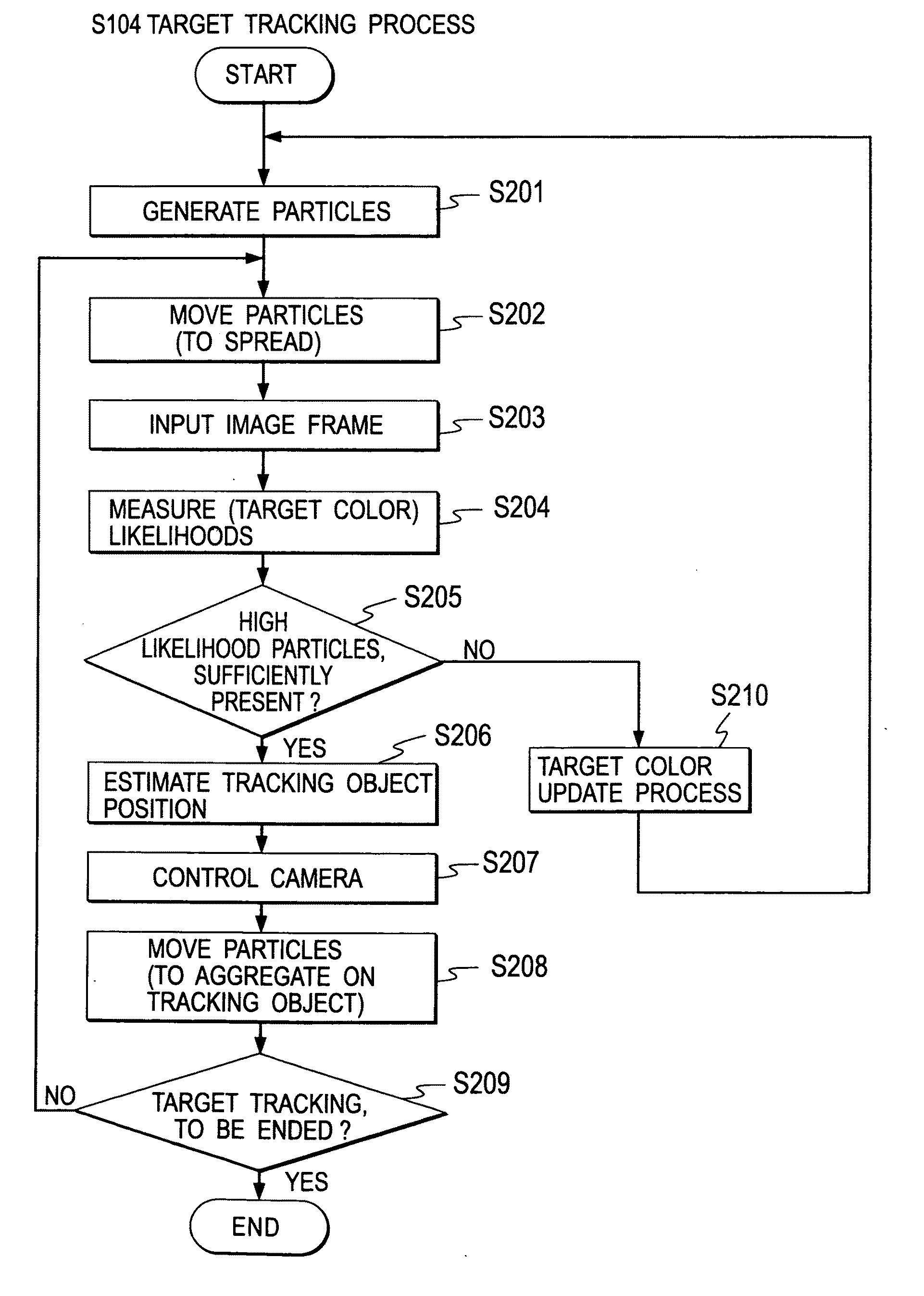
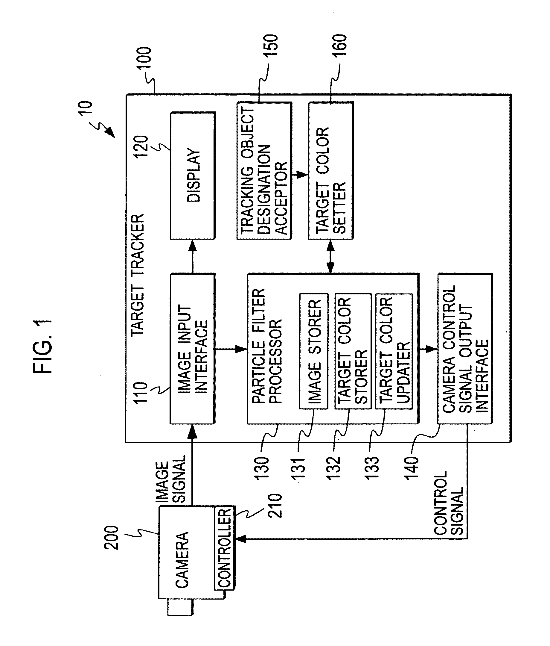
[0036]There will de described preferred embodiments of the present invention with reference to the drawings. FIG. 1 is a block diagram of configuration of a target tracking system 10 including a target tracker 100 according to a first embodiment of the present invention. As illustrated in the figure, the target tracking system 10 includes: the target tracker 100; a camera 200 configured for picking up an angle of view to output signals of a frame of image; and a controller 210 adapted to implement pan and tilt control and zoom factor control of the camera 200 in accordance with control signals from the target tracker 100.

[0037]The target tracker 100 includes: an image input interface 110 configured to input image signals output from the camera 200; a display 120 configured to display a picture based on a frame of input signals; a particle filter processor 130 configured for a process of tracking a target object by use of a particle filter; a camera control signal output interface 14...

second embodiment

[0077]Description is now made of a second embodiment of the present invention. FIG. 9 is a block diagram of configuration of a target tracking system 10a including a target tracker 100a according to the second embodiment. As illustrated in the figure, the target tracking system 10a includes: the target tracker 100a; a camera 200 configured for picking up an angle of view to output signals of a frame of image; and a controller 210 adapted to implement pan and tilt control and zoom factor control of the camera 200 in accordance with control signals from the target tracker 100a.

[0078]The camera 200 as well as the controller 210 may well be identical in configuration to the first embodiment. The target tracker 100a may be substantially identical in configuration to the target tracker 100 in the first embodiment. Accordingly, like components and elements are designated by like reference characters, omitting redundancy.

[0079]The target tracker 100a includes: an image input interface 110 ...

third embodiment

[0097]Description is now made of a third embodiment of the present invention. FIG. 13 is a block diagram of configuration of a target tracking system 10b including a target tracker 100b according to the third embodiment. As illustrated in the figure, the target tracking system 10b includes: the target tracker 100b; a camera 200 configured for picking up an angle of view to output signals of a frame of image; and a controller 210 adapted to implement pan and tilt control and zoom factor control of the camera 200 in accordance with control signals from the target tracker 100b.

[0098]The camera 200 as well as the controller 210 may well be identical in configuration to the first embodiment. The target tracker 100b may be substantially identical in configuration to the target tracker 100 in the first embodiment. Accordingly, like components and elements are designated by like reference characters, omitting redundancy.

[0099]The target tracker 100b includes: an image input interface 110 c...


PUM


Abstract

For a tracking of a target object in a time series of frames of image data, a tracking object designation acceptor accepts a designation of a tracking object, a target color setter sets a color of the designated tracking object as a target color, and a particle filter processor employs particles for measurements to determine color likelihoods by comparison between the target color and colors in vicinities of particles, works, as the color likelihoods meet a criterion, to estimate a region of the tracking object in a frame of image data in accordance with results of the measurements, and as the color likelihoods fails to meet the criterion, to use particles, for measurements to determine luminance likelihoods based on luminance differences between frames of image data in a time series of frames of image data, and estimate a region of the tracking object in a frame of image data in accordance with results of the measurements, and updates the target color by a color in either estimated region.

Description

BACKGROUND OF THE INVENTION[0001]1. Field of the Invention[0002]The present invention relates to a target tracker, and particularly, to a target tracker adapted to track a target object in a time series of frames of image data.[0003]2. Description of the Related Arts[0004]There are practical applications of camera systems making use of images picked up by a camera in a variety of situations, as represented by a picture monitoring system or video conference system. Some of such camera systems have a tracking function of automatically tracking a preset target object, to pick it up, while changing an imaging region of camera. For instance, there are picture monitoring systems provided with a tracking function and adapted, once a suspicious person is caught as a target object, to continue imaging, while tracking the person to pick up in a picture. Further, there are video conference systems provided with a tracking function and adapted to pick up conference images tracking a focused per...

Claims


Application Information

Patent Timeline
Patent Type & Authority Applications(United States)
IPC IPC(8): G06T7/00
CPCG06T7/208G06T2207/30201G06T2207/10024G06T2207/10016G06T7/277
Inventor KIZUKI, TAKAFUMISAKURAI, YOSHITAKA
Owner RAKUTEN GRP INC
Why Eureka
Try Eureka