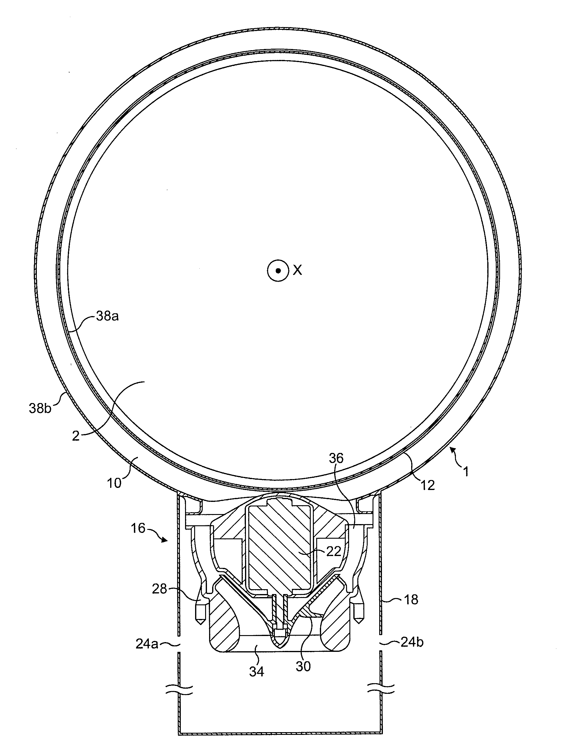
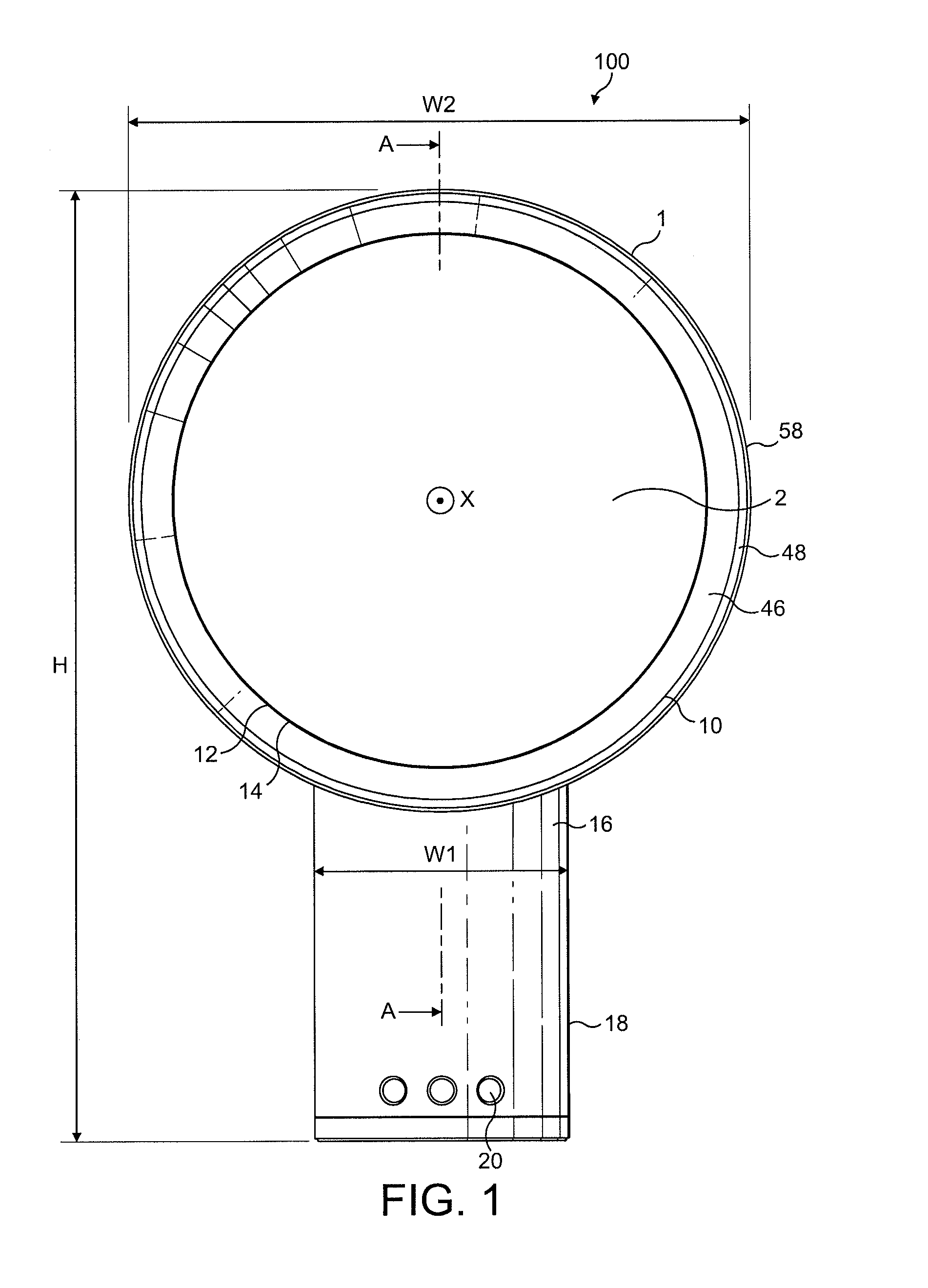
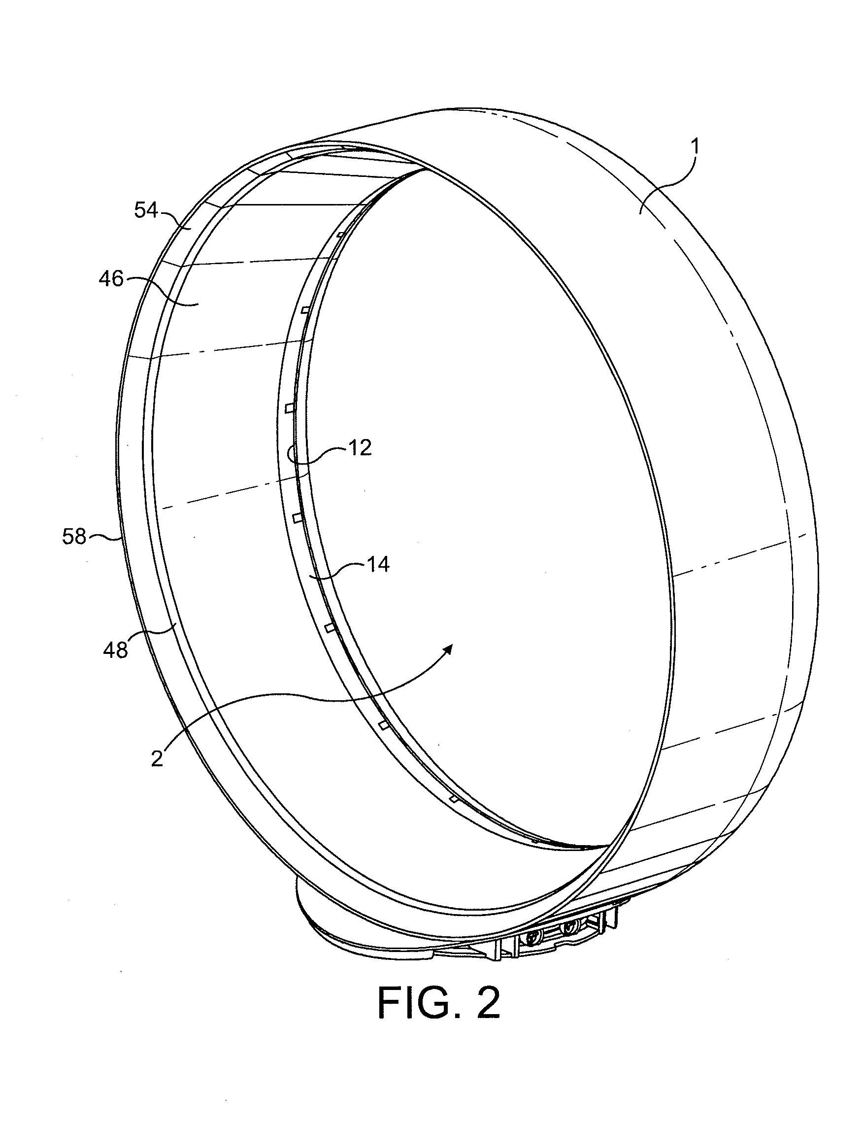
[0039]FIG. 1 illustrates an example of a fan assembly 100 viewed from the front of the device. The fan assembly 100 comprises an annular nozzle 1 defining a central opening 2. With reference also to FIGS. 2 and 3, nozzle 1 comprises an interior passage 10, a mouth 12 and a Coanda surface 14 adjacent the mouth 12. The Coanda surface 14 is arranged so that a primary air flow exiting the mouth 12 and directed over the Coanda surface 14 is amplified by the Coanda effect. The nozzle 1 is connected to, and supported by, a base 16 having an outer casing 18. The base 16 includes a plurality of selection buttons 20 accessible through the outer casing 18 and through which the fan assembly 100 can be operated. The fan assembly has a height, H, width, W, and depth, D, shown on FIGS. 1 and 3. The nozzle 1 is arranged to extend substantially orthogonally about the axis X. The height of the fan assembly, H, is perpendicular to the axis X and extends from the end of the base 16 remote from the nozzle 1 to the end of the nozzle 1 remote from the base 16. In this embodiment the fan assembly 100 has a height, H, of around 530 mm, but the fan assembly 100 may have any desired height. The base 16 and the nozzle 1 have a width, W, perpendicular to the height H and perpendicular to the axis X. The width of the base 16 is shown labelled W1 and the width of the nozzle 1 is shown labelled as W2 on FIG. 1. The base 16 and the nozzle 1 have a depth in the direction of the axis X. The depth of the base 16 is shown labelled D1 and the depth of the nozzle 1 is shown labelled as D2 on FIG. 3.
[0040]FIGS. 3, 4, 5 and 6 illustrate further specific details of the fan assembly 100. A motor 22 for creating an air flow through the nozzle 1 is located inside the base 16. The base 16 further comprises an air inlet 24a, 24b formed in the outer casing 18 and through which air is drawn into the base 16. A motor housing 28 for the motor 22 is also located inside the base 16. The motor 22 is supported by the motor housing 28 and held or fixed in a secure position within the base 16.
[0041]In the illustrated embodiment, the motor 22 is a DC brushless motor. An impeller 30 is connected to a rotary shaft extending outwardly from the motor 22, and a diffuser 32 is positioned downstream of the impeller 30. The diffuser 32 comprises a fixed, stationary disc having spiral blades.
[0042]An inlet 34 to the impeller 30 communicates with the air inlet 24a, 24b formed in the outer casing 18 of the base 16. The outlet 36 of the diffuser 32 and the exhaust from the impeller 30 communicate with hollow passageway portions or ducts located inside the base 16 in order to establish air flow from the impeller 30 to the interior passage 10 of the nozzle 1. The motor 22 is connected to an electrical connection and power supply and is controlled by a controller (not shown). Communication between the controller and the plurality of selection buttons 20 enables a user to operate the fan assembly 100.
[0043]The features of the nozzle 1 will now be described with reference to FIGS. 3, 4 and 5. The shape of the nozzle 1 is annular. In this embodiment the nozzle 1 has a diameter of around 350 mm, but the nozzle may have any desired diameter, for example around 300 mm The interior passage10 is annular and is formed as a continuous loop or duct within the nozzle 1. The nozzle 1 comprises a wall 38 defining the interior passage 10 and the mouth 12. In the illustrated embodiments the wall 38 comprises two curved wall parts 38a and 38b connected together, and hereafter collectively referred to as the wall 38. The wall 38 comprises an inner surface 39 and an outer surface 40. In the illustrated embodiments the wall 38 is arranged in a looped or folded shape such that the inner surface 39 and outer surface 40 approach and partially face, or overlap, one another. The facing portions of the inner surface 39 and the outer surface 40 define the mouth 12. The mouth 12 extends about the axis X and comprises a tapered region 42 narrowing to an outlet 44.
[0044]The wall 38 is stressed and held under tension with a preload force such that one of the facing portions of the inner surface 39 and the outer surface 40 is biased towards the other; in the preferred embodiments the outer surface 40 is biased towards the inner surface 39. These facing portions of the inner surface 39 and the outer surface 40 are held apart by spacers. In the illustrated embodiments the spacers comprise a plurality of spacers 26 which are preferably equally angularly spaced about the axis X. The spacers 26 are preferably integral with the wall 38 and are preferably located on the inner surface 39 of the wall 38 so as to contact the outer surface 40 and maintain a substantially constant spacing about the axis X between the facing portions of the inner surface 39 and the outer surface 40 at the outlet 44 of the mouth 12.
[0045]FIGS. 4 and 5 illustrate two alternative arrangements for the spacers 26. The spacers 26 illustrated in FIG. 4 comprise a plurality of fingers 260 each having an inner edge 264 and an outer edge 266. Each finger 260 is located between the facing portions of the inner surface 39 and the outer surface 40 of the wall 38. Each finger 260 is secured at its inner edge 264 to the inner surface 39 of the wall 38. A portion of the arm 260 extends beyond the outlet 44. The outer edge 266 of arm 260 engages the outer surface 40 of the wall 38 to space apart the facing portions of the inner surface 39 and the outer surface 40.
[0046]The spacers illustrated in FIG. 5 are similar to those illustrated in FIG. 4, except that the fingers 360 of FIG. 5 terminate substantially flush with the outlet 44 of the mouth 12.
[0047]The size of the fingers 260, 360 determines the spacing between the facing portions of the inner surface 39 and the outer surface 40.
[0048]The spacing between the facing portions at the outlet 44 of the mouth 12 is chosen to be in the range from 0.5 mm to 10 mm. The choice of spacing will depend on the desired performance characteristics of the fan. In this embodiment the outlet 44 is around 1.3 mm wide, and the mouth 12 and the outlet 44 are concentric with the interior passage 10.
[0049]The mouth 12 is adjacent a surface comprising a Coanda surface 14. The surface of the nozzle 1 of the illustrated embodiment further comprises a diffuser portion 46 located downstream of the Coanda surface 14 and a guide portion 48 located downstream of the diffuser portion 46. The diffuser portion 46 comprises a diffuser surface 50 arranged to taper away from the axis X in such a way so as to assist the flow of air current delivered or output from the fan assembly 100. In the example illustrated in FIG. 3 the mouth 12 and the overall arrangement of the nozzle 1 is such that the angle subtended between the diffuser surface 50 and the axis X is around 15°. The angle is chosen for efficient air flow over the Coanda surface 14 and over the diffuser portion 46. The guide portion 48 includes a guide surface 52 arranged at an angle to the diffuser surface 50 in order to further aid efficient delivery of cooling air flow to a user. In the illustrated embodiment the guide surface 52 is arranged substantially parallel to the axis X and presents a substantially flat and substantially smooth face to the air flow emitted from the mouth 12.
[0050]The surface of the nozzle 1 of the illustrated embodiment terminates at an outwardly flared surface 54 located downstream of the guide portion 48 and remote from the mouth 12. The flared surface 54 comprises a tapering portion 56 and a tip 58 defining the circular opening 2 from which air flow is emitted and projected from the fan assembly 1. The tapering portion 56 is arranged to taper away from the axis X in a manner such that the angle subtended between the tapering portion 56 and the axis is around 45°. The tapering portion 56 is arranged at an angle to the axis which is steeper than the angle subtended between the diffuser surface 50 and the axis. A sleek, tapered visual effect is achieved by the tapering portion 56 of the flared surface 54. The shape and blend of the flared surface 54 detracts from the relatively thick section of the nozzle 1 comprising the diffuser portion 46 and the guide portion 48. The user's eye is guided and led, by the tapering portion 56, in a direction outwards and away from axis X towards the tip 58. By this arrangement the appearance is of a fine, light, uncluttered design often favoured by users or customers.
[0051]The nozzle 1 extends by a distance of around 5 cm in the direction of the axis. The diffuser portion 46 and the overall profile of the nozzle 1 are based, in part, on an aerofoil shape. In the example shown the diffuser portion 46 extends by a distance of around two thirds the overall depth of the nozzle 1 and the guide portion 48 extends by a distance of around one sixth the overall depth of the nozzle.
[0052]The fan assembly 100 described above operates in the following manner. When a user makes a suitable selection from the plurality of buttons 20 to operate or activate the fan assembly 100, a signal or other communication is sent to drive the motor 22. The motor 22 is thus activated and air is drawn into the fan assembly 100 via the air inlets 24a, 24b. In the preferred embodiment air is drawn in at a rate of approximately 20 to 30 litres per second, preferably around 27 l/s (litres per second). The air passes through the outer casing 18 and along the route illustrated by arrow F′ of FIG. 3 to the inlet 34 of the impeller 30. The air flow leaving the outlet 36 of the diffuser 32 and the exhaust of the impeller 30 is divided into two air flows that proceed in opposite directions through the interior passage 10. The air flow is constricted as it enters the mouth 12, is channelled around and past spacers 26 and is further constricted at the outlet 44 of the mouth 12. The constriction creates pressure in the system. The motor 22 creates an air flow through the nozzle 16 having a pressure of at least 400 kPa. The air flow created overcomes the pressure created by the constriction and the air flow exits through the outlet 44 as a primary air flow.
[0053]The output and emission of the primary air flow creates a low pressure area at the air inlets 24a, 24b with the effect of drawing additional air into the fan assembly 100. The operation of the fan assembly 100 induces high air flow through the nozzle 1 and out through the opening 2. The primary air flow is directed over the Coanda surface 14, the diffuser surface 50 and the guide surface 52. The primary air flow is amplified by the Coanda effect and concentrated or focussed towards the user by the guide portion 48 and the angular arrangement of the guide surface 52 to the diffuser surface 50. A secondary air flow is generated by entrainment of air from the external environment, specifically from the region around the outlet 44 and from around the outer edge of the nozzle 1. A portion of the secondary air flow entrained by the primary air flow may also be guided over the diffuser surface 48. This secondary air flow passes through the opening 2, where it combines with the primary air flow to produce a total air flow projected forward from the nozzle 1.
[0054]The combination of entrainment and amplification results in a total air flow from the opening 2 of the fan assembly 100 that is greater than the air flow output from a fan assembly without such a Coanda or amplification surface adjacent the emission area.
[0055]The distribution and movement of the air flow over the diffuser portion 46 will now be described in terms of the fluid dynamics at the surface.
[0056]In general a diffuser functions to slow down the mean speed of a fluid, such as air, this is achieved by moving the air over an area or through a volume of controlled expansion. The divergent passageway or structure forming the space through which the fluid moves must allow the expansion or divergence experienced by the fluid to occur gradually. A harsh or rapid divergence will cause the air flow to be disrupted, causing vortices to form in the region of expansion. In this instance the air flow may become separated from the expansion surface and uneven flow will be generated. Vortices lead to an increase in turbulence, and associated noise, in the air flow which can be undesirable, particularly in a domestic product such as a fan.
[0057]In order to achieve a gradual divergence and gradually convert high speed air into lower speed air the diffuser can be geometrically divergent. In the arrangement described above, the structure of the diffuser portion 46 results in an avoidance of turbulence and vortex generation in the fan assembly.
[0058]The air flow passing over the diffuser surface 50 and beyond the diffuser portion 46 can tend to continue to diverge as it did through the passageway created by the diffuser portion 46. The influence of the guide portion 48 on the air flow is such that the air flow emitted or output from the fan opening is concentrated or focussed towards user or into a room. The net result is an improved cooling effect at the user.
[0059]The combination of air flow amplification with the smooth divergence and concentration provided by the diffuser portion 46 and guide portion 48 results in a smooth, less turbulent output than that output from a fan assembly without such a diffuser portion 46 and guide portion 48.
[0060]The amplification and laminar type of air flow produced results in a sustained flow of air being directed towards a user from the nozzle 1. In the preferred embodiment the mass flow rate of air projected from the fan assembly 100 is at least 450 l/s, preferably in the range from 600 l/s to 700 l/s. The flow rate at a distance of up to 3 nozzle diameters (i.e. around 1000 to 1200 mm) from a user is around 400 to 500 l/s. The total air flow has a velocity of around 3 to 4 m/s (metres per second). Higher velocities are achievable by reducing the angle subtended between the surface and the axis X. A smaller angle results in the total air flow being emitted in a more focussed and directed manner. This type of air flow tends to be emitted at a higher velocity but with a reduced mass flow rate. Conversely, greater mass flow can be achieved by increasing the angle between the surface and the axis. In this case the velocity of the emitted air flow is reduced but the mass flow generated increases. Thus the performance of the fan assembly can be altered by altering the angle subtended between the surface and the axis X.
[0061]The invention is not limited to the detailed description given above. Variations will be apparent to the person skilled in the art. For example, the fan could be of a different height or diameter. The base and the nozzle of the fan could be of a different depth, width and height. The fan need not be located on a desk, but could be free standing, wall mounted or ceiling mounted. The fan shape could be adapted to suit any kind of situation or location where a cooling flow of air is desired. A portable fan could have a smaller nozzle, say 5 cm in diameter. The device for creating an air flow through the nozzle can be a motor or other air emitting device, such as any air blower or vacuum source that can be used so that the fan assembly can create an air current in a room. Examples include a motor such as an AC induction motor or types of DC brushless motor, but may also comprise any suitable air movement or air transport device such as a pump or other device for providing directed fluid flow to generate and create an air flow. Features of a motor may include a diffuser or a secondary diffuser located downstream of the motor to recover some of the static pressure lost in the motor housing and through the motor.
[0062]The outlet of the mouth may be modified. The outlet of the mouth may be widened or narrowed to a variety of spacings to maximise air flow. The spacers or spacers may be of any size or shape as required for the size of the outlet of the mouth. The spacers may include shaped portions for sound and noise reduction or delivery. The outlet of the mouth may have a uniform spacing, alternatively the spacing may vary around the nozzle. There may be a plurality of spacers, each having a uniform size and shape, alternatively each spacer, or any number of spacers, may be of different shapes and dimensions. The spacers may be integral with a surface of the nozzle or may be manufactured as one or more individual parts and secured to the nozzle or surface of the nozzle by gluing or by fixings such as bolts or screws or snap fastenings, other suitable fixing means may be used. The spacers may be located at the mouth of the nozzle, as described above, or may be located upstream of the mouth of the nozzle. The spacers may be manufactured from any suitable material, such as a plastic, resin or a metal.
[0063]The air flow emitted by the mouth may pass over a surface, such as Coanda surface, alternatively the airflow may be emitted through the mouth and be projected forward from the fan assembly without passing over an adjacent surface. The Coanda effect may be made to occur over a number of different surfaces, or a number of internal or external designs may be used in combination to achieve the flow and entrainment required. The diffuser portion may be comprised of a variety of diffuser lengths and structures. The guide portion may be a variety of lengths and be arranged at a number of different positions and orientations to as required for different fan requirements and different types of fan performance. The effect of directing or concentrating the effect of the airflow can be achieved in a number of different ways; for example the guide portion may have a shaped surface or be angled away from or towards the centre of the nozzle and the axis X.
[0064]Other shapes of nozzle are envisaged. For example, a nozzle comprising an oval, or ‘racetrack’ shape, a single strip or line, or block shape could be used. The fan assembly provides access to the central part of the fan as there are no blades. This means that additional features such as lighting or a clock or LCD display could be provided in the opening defined by the nozzle.
[0065]Other features could include a pivotable or tiltable base for ease of movement and adjustment of the position of the nozzle for the user.