Multitube catheter

a multi-tube catheter and catheter tube technology, which is applied in the direction of multi-lumen catheters, intravenous devices, medical syringes, etc., can solve the problems of increased catheterization procedure risks, leakage of catheter tubes, and only possible techniques

Active Publication Date: 2010-06-17
IP CATHETER HLDG CO LTD
View PDF12 Cites 2 Cited by
  • Summary
  • Abstract
  • Description
  • Claims
  • Application Information

AI Technical Summary

Benefits of technology

[0030]The way of fusion and the degree of heat and pressure applied, can allow the catheter tubes to be releasable joined and longitudinally split from each other. The tubes are fused together by use of heat sensitive tube slides over the tubes while metallic mandrels are passed through each tube lumen to protect the lumens during fusion. The heat sensitive tube will generate pressure once heat is applied. Continual heating will melt / reshape the catheter tubes inside the heat sensitive tube. After cooling the heat sensitive tube is removed around the catheter tube. The metallic mandrels are then pulled back. The tubes, forming the one catheter tube are separated at each end. The end result is a multitube tube catheter that has a distal split end.
[0031]In one aspect of the present invention, the assembly includes the fusion between a first tube and a shorter second tube to form one catheter tube. Each tube has at least one lumen extending longitudinally through the catheter. The way of fusion and the degree of heat and pressure applied, allow the catheter tubes to be unreleasably joined. The tubes are fused together by use of heat sensitive tube slides over the tubes while metallic mandrels are passed through each tube lumen to protect the lumens during fusion. The heat sensitive tube will generate pressure once heat is applied. Continual heating will melt / reshape the catheter tubes inside the heat sensitive tube. After cooling, the heat sensitive tube is removed around the catheter tube. The metallic mandrels are then pulled back. The end result is a multitube tube catheter has a distal stepped end.
[0039]In another aspect of the invention, the absence of a connector or a hub between the catheter shaft and extension line allows the catheter to be advanced and positioned to any desirable length, then fixed with any fixation devices.

Problems solved by technology

However, this technique is only possible in cases where the catheter is of a relatively small diameter, made of a stiff material and not significantly larger than the guide wire, for example, for insertion of small diameter dual lumen catheters.
The double catheter assembly, while comfortable for the patient, due to its soft durometer, and very effective for Haemodialysis, typically requires multiple procedures and incisions for insertion and / or for tunneling, which increases the attendant risks of the catheterization procedure.
Further, in the case of side-by-side placement of two catheter tubes through a single insertion site in a vessel, while minimizing the number of procedures, can present a potential for leakage between the catheter tubes at the point where the catheter tubes pass into the vessel.
Further, the softer durometer of such catheters, which are typically made of a silicone or a similar material, reduces the risk of vessel wall damage.
Further, since the retaining sleeve is located outside the vessel when in place to provide the self-retaining feature, at the point of entry into the vessel, the catheters are side-by-side in the manner of a standard Tesio catheter, and there still remains the potential risk of blood leakage between the catheters at the vessel site.

Method used


Image

  • Multitube catheter
  • Multitube catheter
  • Multitube catheter

Examples


first embodiment

A First Embodiment

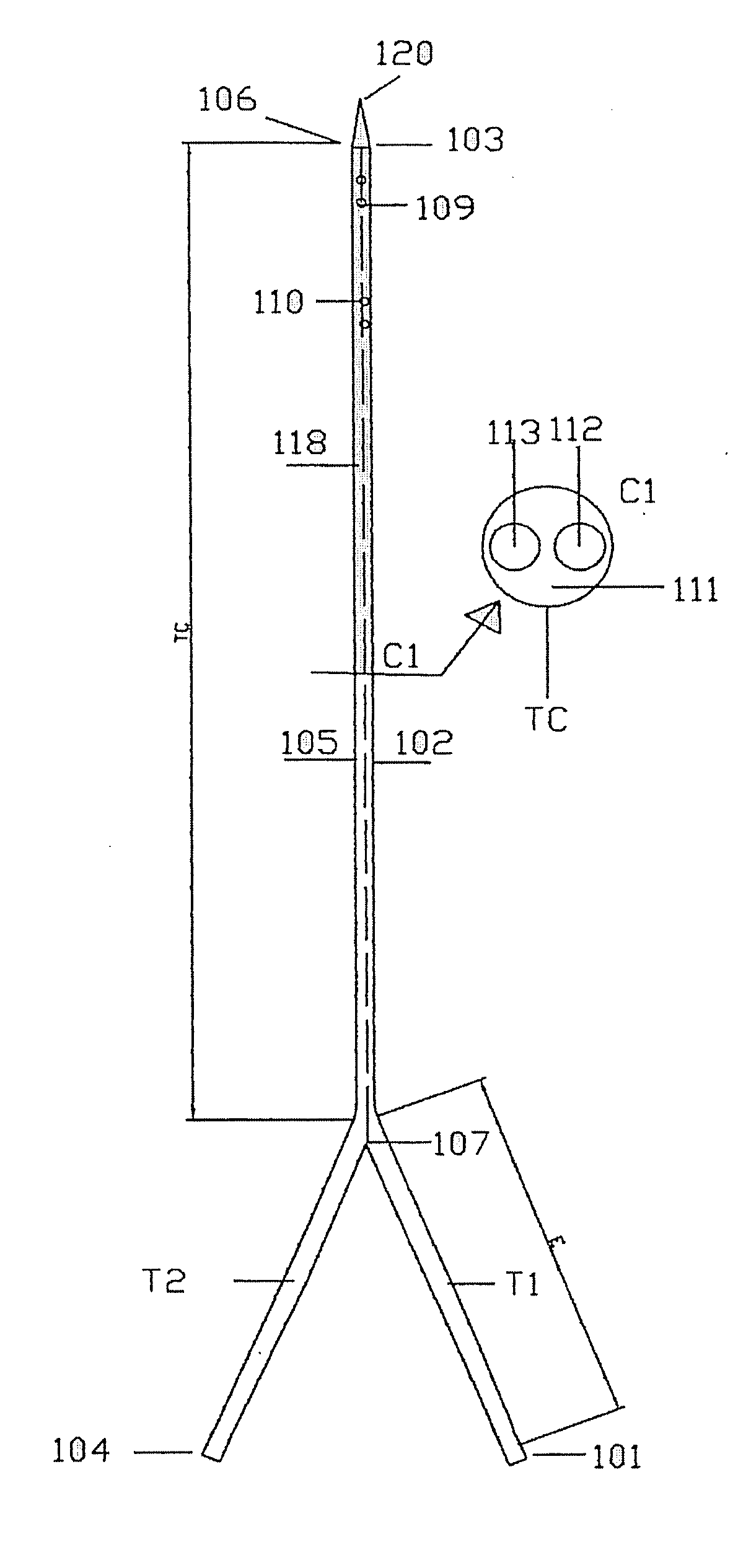
[0052]FIG. 1 illustrates one embodiment of the present invention, where a catheter assembly has at least two lumens. The illustration of two lumens is exemplary, and the scope of the invention encompasses catheters having more than two lumens.

[0053]The catheter assembly includes first tube T1 which has a proximal end 101 and a distal end 103. The catheter assembly includes second tube T2 which has a proximal end 104 and a distal end 106. The first tube T1 and the second tube T2 are united (fused) at catheter shaft TC as a result of fusion of a portion 104 of first tube T1 and the 105 of second tube T2.

[0054]The catheter assembly can be provided (manufactured) so that the first distal end tube D1 and the second distal end tube D2 are splitable (releasably attached) or separate at their respective distal ends. Splitable is defined as releasably attached, meaning the first and the second distal end tubes D1 and D2 are fused, or otherwise attached, so that only minor f...

second embodiment

A Second Embodiment

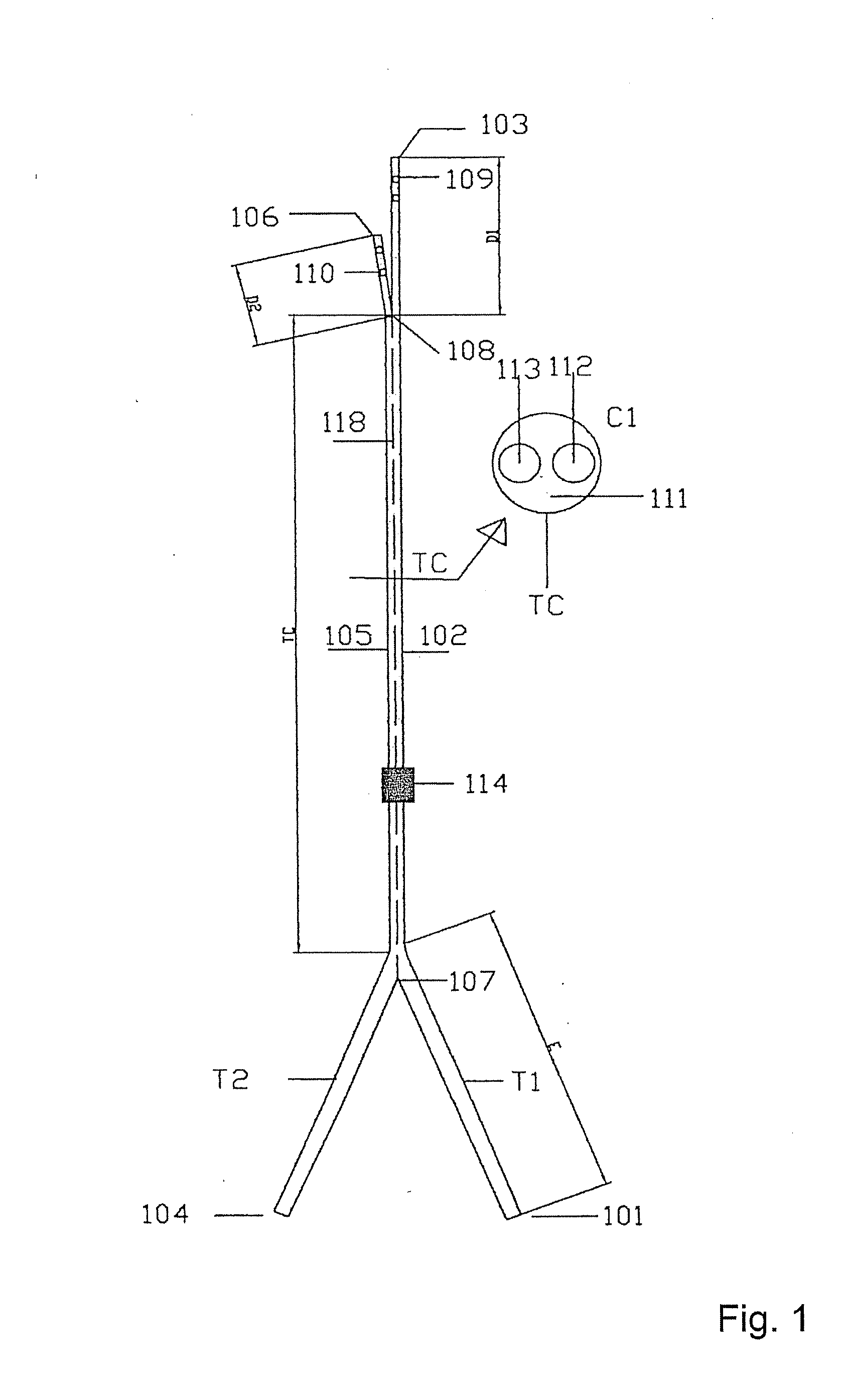
[0067]FIG. 2 illustrates another embodiment of the present invention, where a catheter assembly has at least two lumens. The illustration of two lumens is exemplary, and the scope of the invention encompasses catheters having more than two lumens.

[0068]The catheter assembly includes first tube T1 which has a proximal end 101 and a distal end 103. The catheter assembly includes a shorter second tube T2 which has a proximal end 104 and a distal end 106. The first tube T1 and the second tube T2 are united (fused) at catheter shaft TC as a result of fusion of a portion 104 of first tube T1 and the 105 of second tube T2.

[0069]The catheter assembly can be provided (manufactured) so that the first distal end tube D1 is extending distally beyond the second tube distal end 106.

[0070]The multilumen catheter assembly includes a first lumen 112 and a second lumen 113 extending longitudinally therethrough as illustrated at C1.

[0071]The first lumen 112 is continuous with and th...

third embodiment

A Third Embodiment

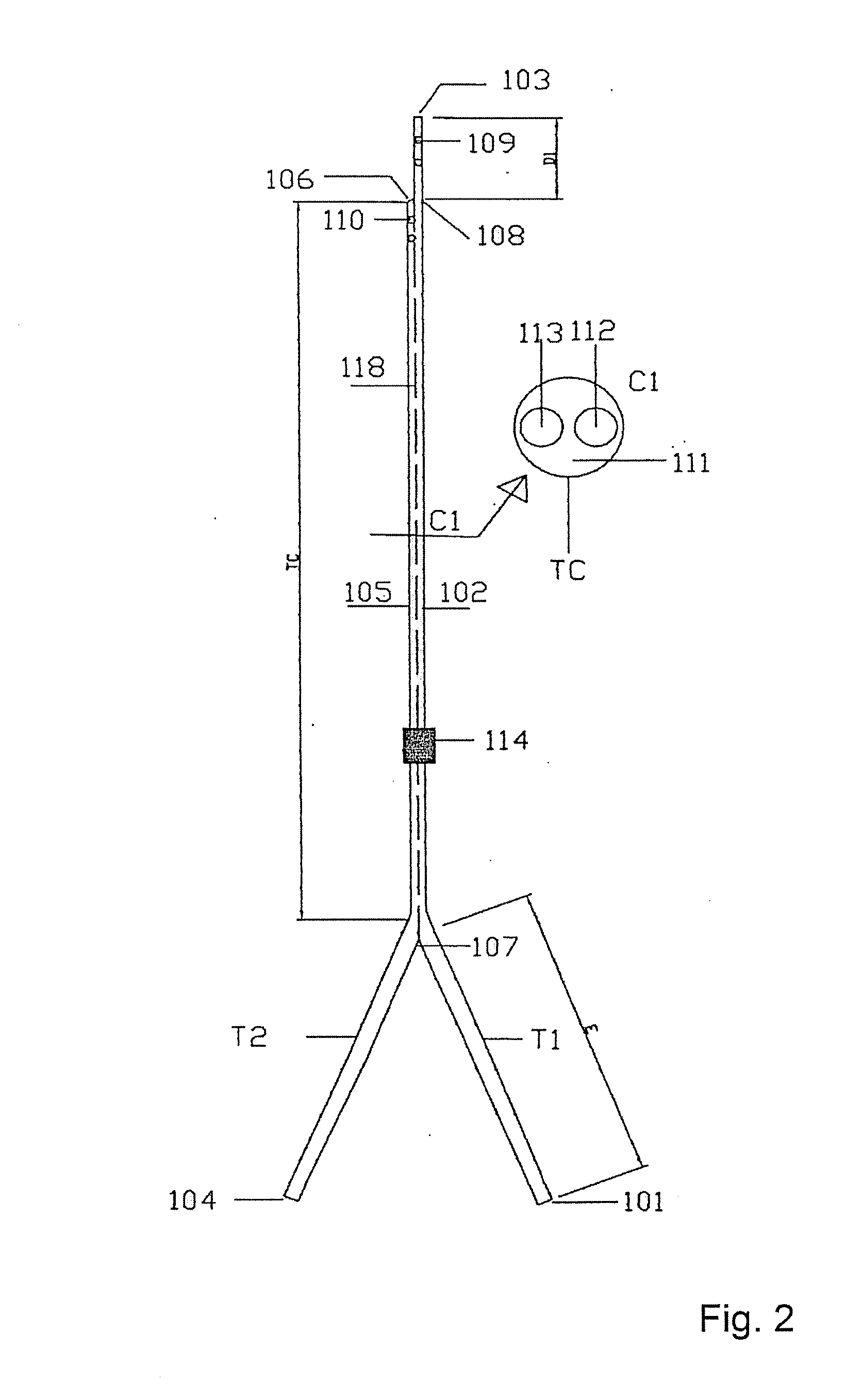
[0081]FIG. 3 illustrates another embodiment of the present invention, where a catheter assembly has at least two lumens. The illustration of two lumens is exemplary, and the scope of the invention encompasses catheters having more than two lumens.

[0082]The catheter assembly includes first tube T1 which has a proximal end 101 and a distal end 103. The catheter assembly includes a second tube T2 which has a proximal end 104 and a distal end 106. The first tube T1 and the second tube T2 are united (fused) at catheter shaft TC as a result of fusion of a portion 104 of first tube T1 and the 105 of second tube T2.

[0083]The catheter assembly can be provided (manufactured) so that the first tube T1 and the second tube T2 are fused along a portion extending from the point 107 to the end of both tubes 103, 106 so as to have a common distal end.

[0084]The assembly according to the third embodiment includes tipping of the distal end of the catheter shaft TC to form a distal cat...


PUM


Abstract

A multitube catheter is provided. The assembly includes two or more tubes fused together to form one catheter tube shaft. Each tube has at least one lumen extending longitudinally through the catheter from its distal end to its proximal end. The tubes are fused together by use of heat and pressure. A distal end of the united catheter tube can be split to form a split tip, stepped tip, or a tapered tip. The proximal segment (non-fused portion) forms catheter extension legs.

Description

FIELD OF THE INVENTION[0001]The present invention relates generally to multitube catheter assemblies, and more particularly to multitube catheter assemblies having distal split independent free floating tip end, a stepped tip end, or a tapered tip end for positioning within an area to be catheterized[0002]The lumens of the multitube catheter are fully circular where they extend through the distal end, the catheter main stem and the proximal end of the extension part.[0003]The presented multitube catheter may be used in any medical field where access to the central venous system is required like haemodialysis, haemofiltration, plasma exchange, chemotherapy infusion, etc.BACKGROUND OF THE INVENTION(A) Technical Background[0004]Catheters for the introduction or removal of fluids may be located in various venous locations and cavities throughout the body for the introduction or removal of fluids. Such catheterization may be performed by using a single catheter having multiple lumens. A ...

Claims


Application Information

Patent Timeline
Patent Type & Authority Applications(United States)
IPC IPC(8): A61M25/00
CPCA61M25/0009A61M2025/0031A61M1/3661A61M2025/0037A61M2025/0034
Inventor HAMBOLY, M. SAMY AHMED
Owner IP CATHETER HLDG CO LTD
Why Eureka
Try Eureka