Journal housing for a cylindrical bearing and related method

a cylindrical bearing and journal housing technology, applied in the direction of sliding contact bearings, rigid support of bearings, mechanical equipment, etc., can solve the problems of compromising the sealing of packing rings, and achieve the effect of reducing flush fluid leakage and increasing the useful working life of journal housings

Active Publication Date: 2015-05-21
ANDRITZ INC
View PDF6 Cites 0 Cited by
  • Summary
  • Abstract
  • Description
  • Claims
  • Application Information

AI Technical Summary

Benefits of technology

[0015]The problem of flush fluid leakage due to creep in pressurized pack-boxes rotary machinery is mitigated by using a pack-box that includes a rotary bearing made of a material having a known coefficient of thermal expansion in a transverse direction, wherein the rotary bearing has at least one shoulder extending from the body of the rotary bearing, wherein the shoulder has a shoulder circumference greater than a body circumference, and wherein the rotary bearing is transversely fixed within the pack-box such that the rotary bearing may not slide transversely within the pack-box. Within the pack-box, there is a wall-step defining first thermal expansion channel adjacent to a bottom of the rotary bearing, wherein the first thermal expansion channel is configured to receive the rotary bearing expanding in a first transverse direction. Within the pack-box, there is also an inner wall defining a second thermal expansion channel adjacent to a shoulder end of the rotary bearing, wherein the second thermal expansion channel is configured to receive the rotary bearing expanding in a second transverse direction. Both thermal expansion channels can be configured to accommodate a predetermined amount of transverse rotary bearing expansion. In other embodiments, only the first thermal expansion channel may be configured to accommodate a predetermined amount of transverse rotary bearing expansion. In yet other embodiments, only the second thermal expansion channel may be configured to accommodate a predetermined amount of transverse rotary bearing expansion.
[0016]A pack-box in accordance with the present disclosure may be used in either low-rpm rotary machinery or high rpm rotary machinery. Low-rpm machinery may have journals that rotate in a range of about 0 rpm to about 100 rpm. Low-rpm machines may have journals that rotate at a linear speed of up to 20 meters per second (mps). High-rpm machinery may have journals that rotate at a rate greater than 100 rpm. Temperatures within typical low-rpm pack-boxes under normal operating conditions may range from about 140 degrees Celsius to about 200 degrees Celsius. In high-rpm pack-box houses, the temperature may exceed 200 degrees Celsius. In certain exemplary embodiments, the pressure within the pack-box may range from about 6 bar to about 25 bar. In other exemplary embodiments, the pack-box may be a high-pressure pack-box, configured to accommodate pressures ranging from about to 25 bar to about 42 bar. In other exemplary embodiments, the rotary bearings may be used in journal housings that operate under, or contain a vacuum. A pack-box and rotary bearing in accordance with the present disclosure may allow for rotary bearings to expand to a desirable length during known operating conditions.
[0017]It is an object of this disclosure to provide for desirable transverse expansion of the rotary bearing. It is also an object of this disclosure to reduce flush fluid leaks caused by overly compressed packing rings in pack-boxes. This disclosure also describes apparatuses and methods for increasing the useful working life of journal housings and rotary machinery generally, and pack-box, packing rings, journals, rotary bearings, and other components within the pack-box, including sleeves in particular.

Problems solved by technology

Briefly, because cooled packing rings may decompress axially but not sufficiently transversely, a periodic loosening of the packing gland follower would likely compromise the packing ring seals.

Method used


Image

  • Journal housing for a cylindrical bearing and related method
  • Journal housing for a cylindrical bearing and related method
  • Journal housing for a cylindrical bearing and related method

Examples


Embodiment Construction

[0035]The following detailed description of the preferred embodiments is presented only for illustrative and descriptive purposes and is not intended to be exhaustive or to limit the scope and spirit of the invention. The embodiments were selected and described to best explain the principles of the invention and its practical application. A person of ordinary skill in the art will recognize that many variations can be made to the invention disclosed in this specification without departing from the scope and spirit of the invention.

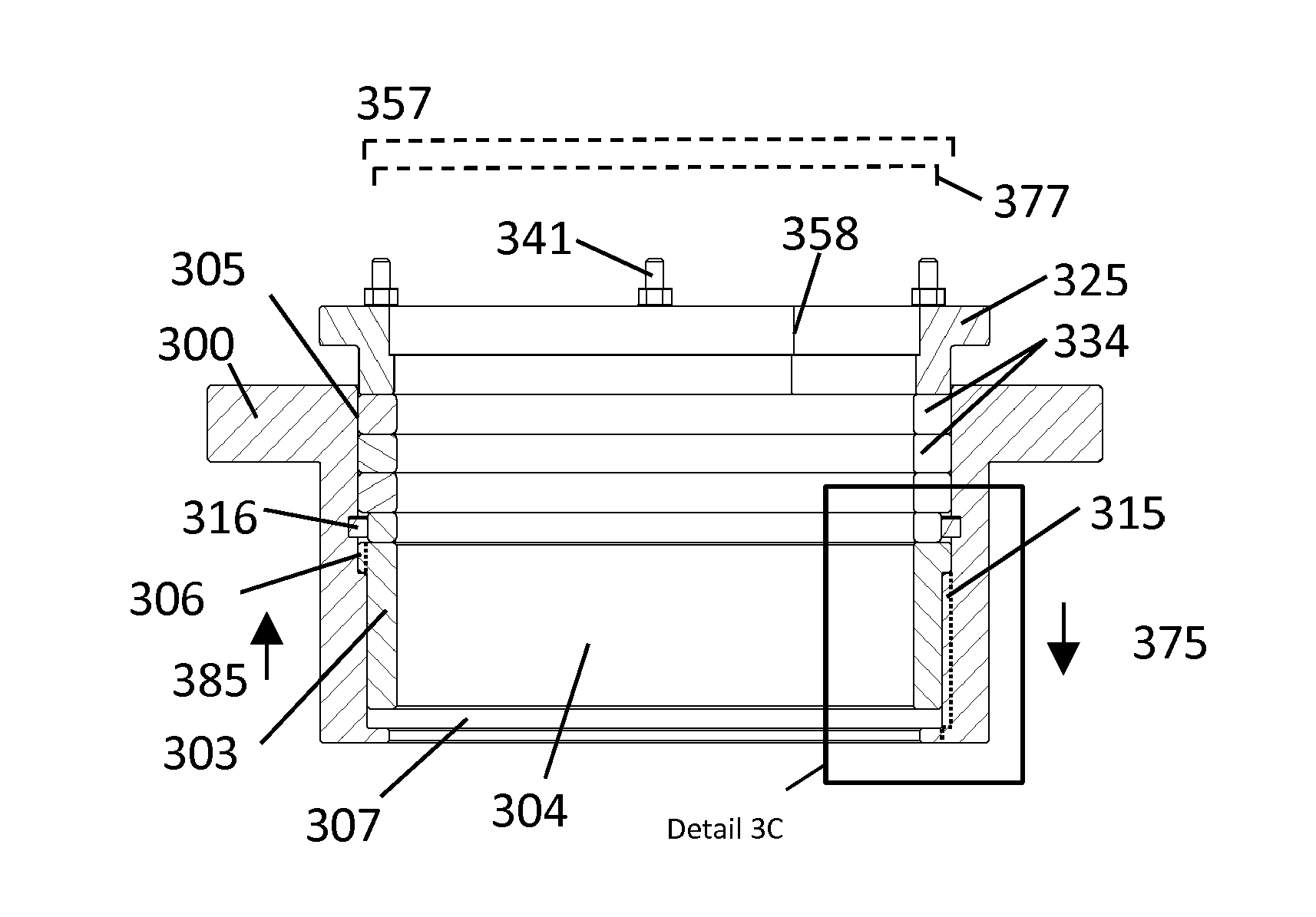
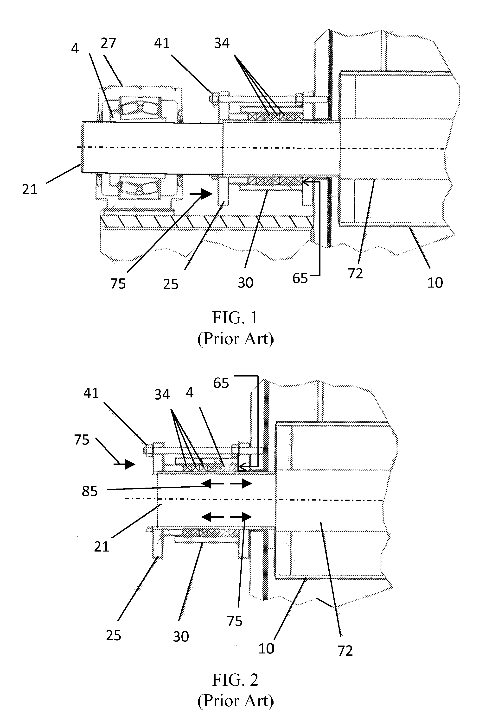
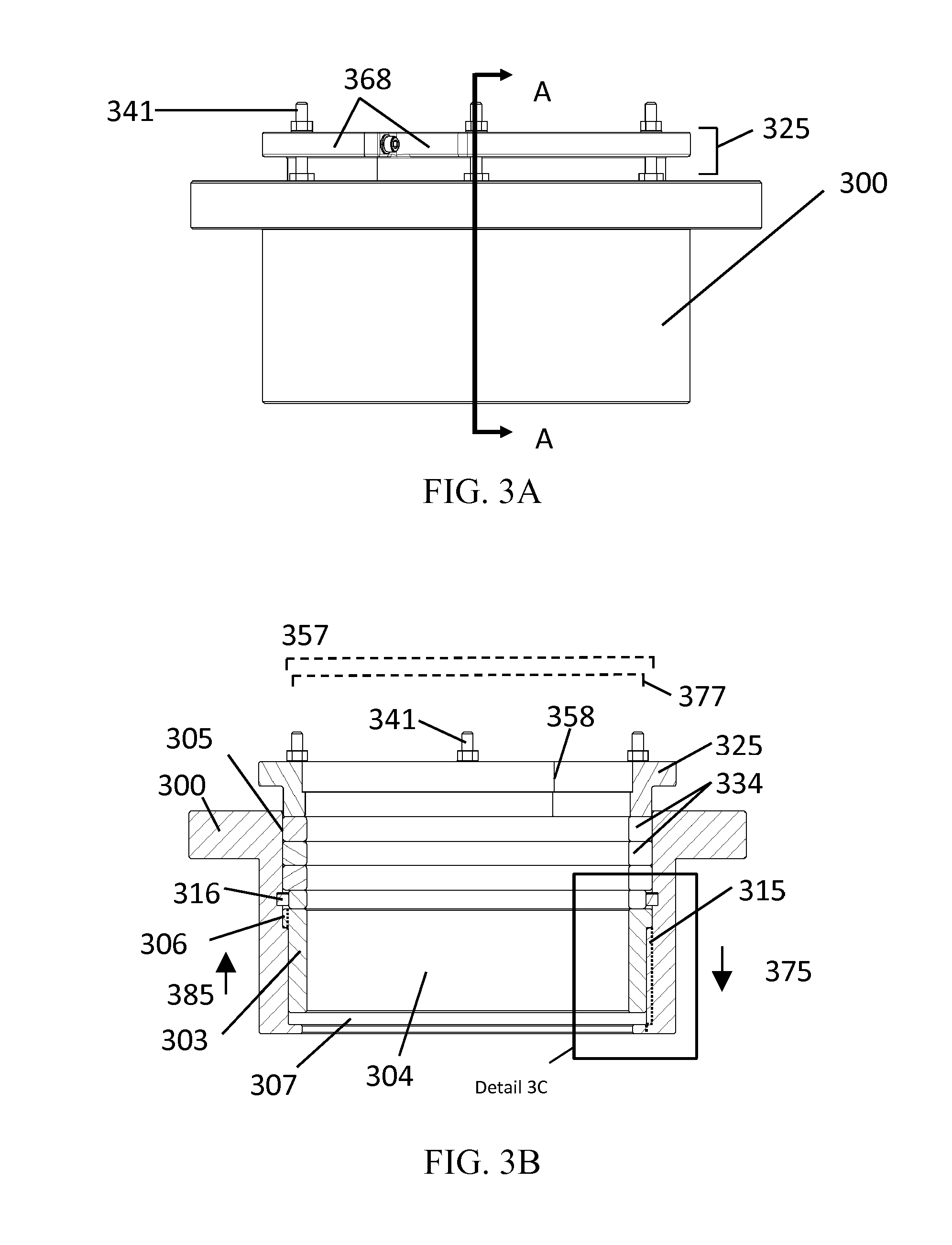
[0036]The illustrative embodiments of the pack-box in accordance with this disclosure are shown in FIGS. 3 to 5. The present disclosure describes a pack-box suitable for use in rotary machinery in which the pack-box operates under positive or negative pressure, and methods for using the same. Although a pack-box is described, nothing in this disclosure prevents the invention from being used in a journal housing that does not contain packing rings. Currentl...


PUM

PropertyMeasurementUnit
pressureaaaaaaaaaa
temperatureaaaaaaaaaa
pressureaaaaaaaaaa

Abstract

To address the problem of flush fluid leakage under normal operating conditions in rotary machinery, an improved pack-box has been conceived. The pack-box has a rotary bearing concentrically disposed within the pack-box, wherein a circumferential segment of the rotary bearing is circumferentially fixed within the pack-box. The pack-box further comprises a wall-step that defines at least a first thermal expansion channel and an inner wall that defines at least a second thermal expansion channel.

Description

CROSS-RELATED APPLICATION[0001]This application claims the benefit of U.S. Provisional Patent Application Ser. No. 61 / 905,650 filed on Nov. 18, 2013, the entirely of which is incorporated herein by reference.BACKGROUND OF THE INVENTION[0002]1. Technical Field[0003]The present disclosure relates generally to a method and apparatus for reducing packing ring creep and fluid leakage in rotary machinery and more particularly to rotary bearings and pack-boxes used in low revolutions per minute (rpm) rotary machinery common in the pulp and paper and biofuel industries.[0004]2. Related Art[0005]In industries that use rotary machines—particularly large rotary machines having pressurized journal housings—it can be desirable to separate flush fluid commonly used in journal housings from process fluids commonly used in the body of the rotary machine.[0006]Rotary bearings are usually disposed around the journal and are typically designed to reduce rotational friction caused by the spinning journ...

Claims


Application Information

Patent Timeline
Patent Type & Authority Applications(United States)
IPC IPC(8): F16C35/02F16C43/02F16C33/74F16C17/02F16C33/20
CPCF16C35/02F16C17/02F16C43/02F16C33/74F16C33/20F16C17/22F16J15/164F16J15/184Y10T29/49647
Inventor BOLZ, EDWIN WILLIAM
Owner ANDRITZ INC
Why Eureka
Try Eureka