Optical depilation apparatus

Inactive Publication Date: 2010-06-17
PANASONIC CORP
View PDF10 Cites 11 Cited by
  • Summary
  • Abstract
  • Description
  • Claims
  • Application Information

AI Technical Summary

Benefits of technology

[0005]It is another object of the present invention to provide an optical depilation app

Problems solved by technology

However, with the above-described configuration, although the posture of the optical depilation apparatus during light irradiation can be accurately corrected, safety measures taken to prevent the ligh

Method used


Image

  • Optical depilation apparatus
  • Optical depilation apparatus
  • Optical depilation apparatus

Examples


Embodiment Construction

[0014]The best mode for carrying out the invention will be described below in greater detail with reference to the appended drawings.

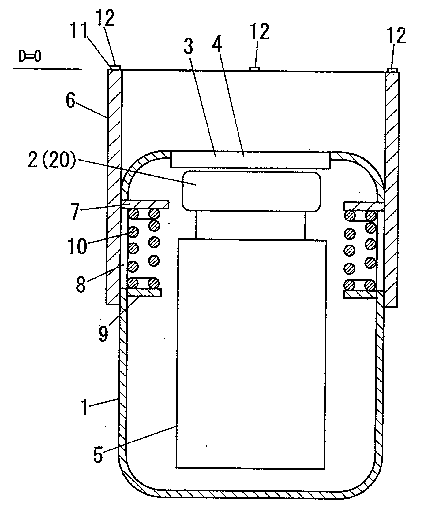
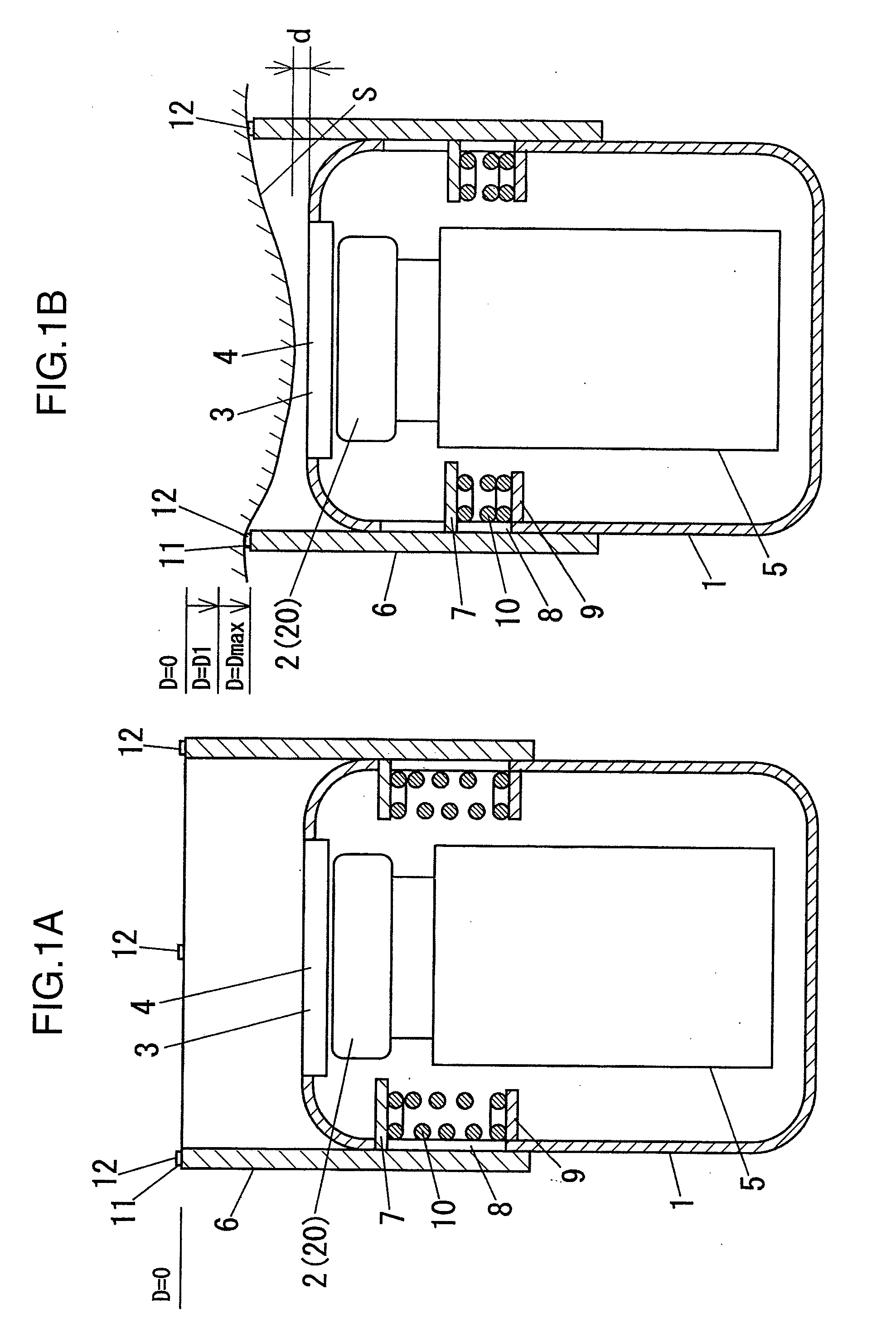
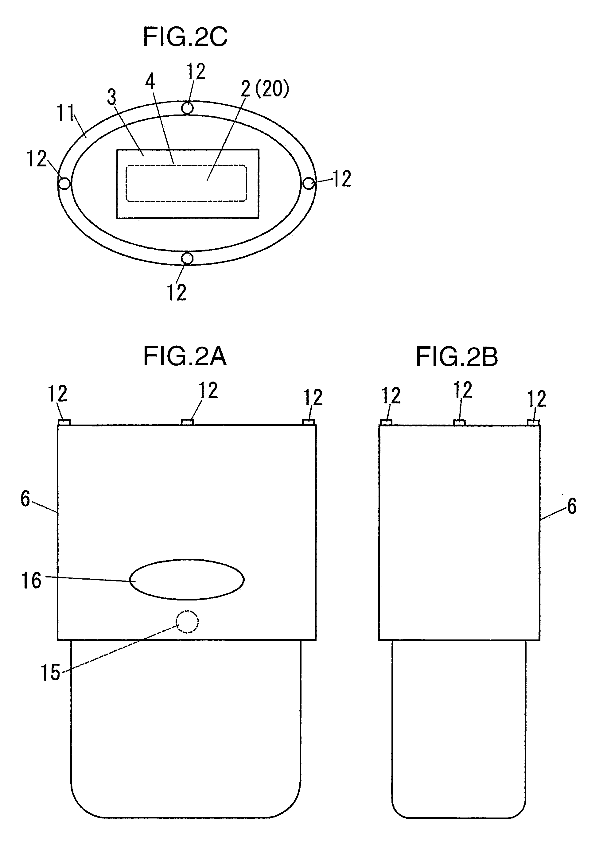
[0015]FIGS. 1A, 1B to FIGS. 3A, 3B illustrate schematically an embodiment of the optical depilation apparatus in accordance with the present invention. The optical depilation apparatus of the present embodiment is provided with a box-shaped apparatus body 1 that can be grasped by one hand. A flashlight 2 composed of a xenon light lamp is accommodated as a light source unit 20 in the apparatus body 1. A light irradiation port 3 is opened in a position close to the flashlight 2 at the distal end of the apparatus body 1. Pulsed flashes generated by the flashlight 2 are emitted through the light irradiation port 3 to the outside of the apparatus body 1. A transparent lamp cover 4 is fitted in the light irradiation port 3. The flashes emitted from the flashlight 2 are emitted through the lamp cover 4 to the outside of the apparatus body 1. The flashes are e...


PUM


Abstract

An optical depilation apparatus is used for performing depilation by irradiating skin with light. The apparatus has: a light source unit; a light irradiation port; and an apparatus body emitting light from the light source unit through the light irradiation port; a light shielding part disposed so as to surround the light irradiation port of the apparatus body; and a support part that supports the light shielding part so as to allow the light shielding part to move in the light irradiation direction with respect to the apparatus body. The support part has a receiving portion provided at the apparatus body, a convex portion provided at the light shielding part, and a spring member disposed between the receiving part and the convex part.

Description

TECHNICAL FIELD[0001]The present invention relates to an optical depilation apparatus that performs depilation by irradiating skin with light.BACKGROUND ART[0002]An optical depilation apparatus in which hair papilla is heated by transferring light energy emitted by a laser diode or a flashlight to the hair, thereby making it difficult for nutrients to reach the hair, is known as a device for performing depilation. In such an optical depilation apparatus, irradiation with light has to be conducted from the direction perpendicular to the skin surface. Accordingly, in the optical depilation apparatus disclosed in Patent Document 1 or Patent Document 2 below, a plurality of contact sensors are disposed in positions surrounding the laser beam irradiation portion of the distal end of the apparatus, the optical depilation apparatus is determined to have a perpendicular posture when the contact sensors detect contact with the skin surface, and the laser beam irradiation is then started.[000...

Claims


Application Information

Patent Timeline
IPC IPC(8): A61B18/18
CPCA45D26/00A45D2200/205A61B18/203A61B2018/00452A61B2019/465A61B2018/1807A61B2019/306A61B2019/409A61B2018/00476A61B2090/049A61B2090/036A61B2090/065
Inventor FUJIKAWA, SHOJI
Owner PANASONIC CORP
Why Eureka
Try Eureka